
 Precision Tools for Demanding Applications
Document No. AD-230MitisConversion-2020 | Rev. EN-03.1
Precision Tools for Demanding Applications
Document No. AD-230MitisConversion-2020 | Rev. EN-03.1
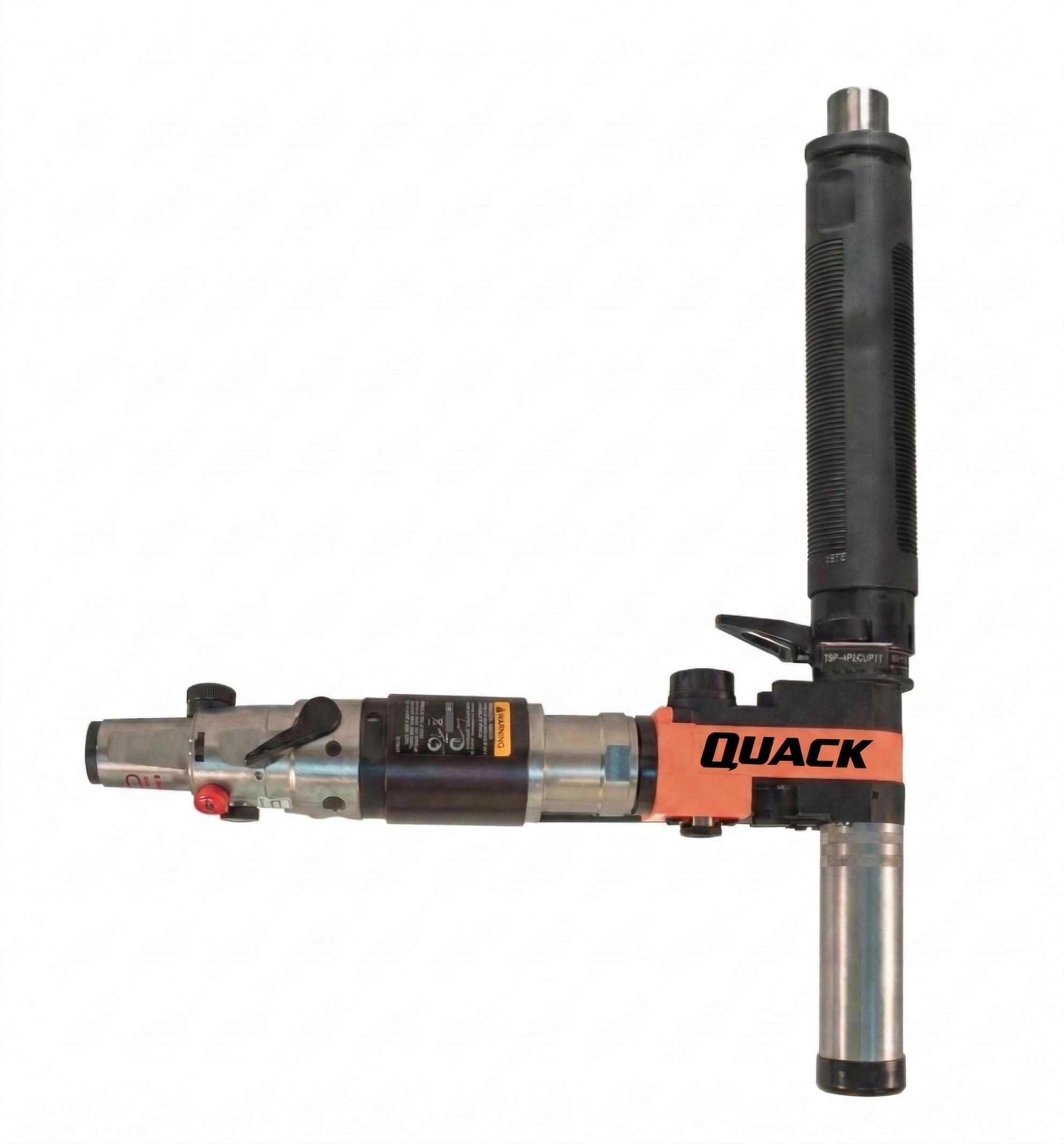
This is a conversion kit for a positive feed drill that is designed for fixtured drilling applications.
This equipment must not be modified in any manner unless approved in writing by Corvaer. All safety devices must be properly installed and maintained in good working order.
Any abuse or misuse of this equipment can cause equipment damage, death, or serious injury. Failure to observe all safety warnings could result in equipment failure or personnel injury.
For additional product safety information refer to Corvaer document CE-2009, General Safety Fixtured Drills.
These safety instructions must be accessible to the operator at all times. They must be shown and made available to all personnel involved in the operation of this equipment.
The operator must read and understand the safety instructions contained in this document before operating this equipment.
These safety instructions are not intended to be all inclusive. Study and comply with all applicable Federal, State, and local regulations.
Do not remove any labels from this equipment. Replace any label that has been damaged and cannot be easily read.
To avoid serious injury, keep hands free from rotating equipment.
Before operating this equipment, coordinate with your workplace safety professional to conduct a hazard assessment of the setup, operation, emergency shut down, start-up, and maintenance of this equipment prior to use. Always use identified safeguards, tooling, and safety procedures identified in the hazard assessment before operating this tool.
Only qualified and trained personnel should install, adjust, repair or use this equipment.
Do not exceed equipment ratings. Never attempt to operate this equipment at more than its rated capacity. Overloading will cause equipment failure and possible personnel injury.
Refer also to the Operation Instructions supplied with the tool for complete instructions of Operation and Use.
This equipment should be stored at temperatures of +40°–+100° F (4°–38° C) with a maximum relative humidity of 80%.
Observe all local disposal guidelines for all components of this equipment and its packaging.
Indicates an imminent hazardous situation which, if not avoided, will result in serious injury or death.
Indicates a potentially hazardous situation which, if not avoided, could result in serious injury or death.
Indicates a potentially hazardous situation which, if not avoided, may result in minor or moderate injury or property damage.
If the tool is supplied with dedicated equipment, adhere to the following instructions as well as all safety instructions:
The gaps should be checked periodically to ensure proper tool performance. It is recommended for reaming/countersinking that the maximum gap be 1.3 times (1.5 in drilling) the initial maximum gap (generally H7/g6 by design) between the spindle and bushing.
Check that the jigs are clean without excessive gap and for concentric collet equipment without oil.
For optimal results, the cutter should be checked regularly:
Implement a comprehensive safety maintenance program to provide regular inspection for all phases of tool operation and air supply equipment. Replace worn or damaged parts using only genuine Quackenbush replacement parts manufactured by Corvaer. The use of parts other than those provided by the manufacturer may result in a drop in output or increased maintenance and may cancel the manufacturer’s warranty.
Never lubricate the tool with flammable or volatile liquid (gasoil, aircraft fuel, etc.). Disconnect the air supply before performing any maintenance on this equipment.
Only qualified and trained personnel should repair this equipment. Refer to the Sales and Service Center listing (Section 4) for authorized Corvaer repair facilities.
Corvaer reserves the right to modify, supplement or improve this document or the product without prior notice. This document may not be reproduced in any way, shape or form, in full or in part, or copied to another natural or machine readable language or to a data carrier, whether electronic, mechanical, optical or otherwise without the express permission of Corvaer.
The 230QRM Mitis conversion updates a standard 230QR positive feed drill to the 230QRM version, adding the Mitis slip-clutch feed mechanism for controlled chip evacuation.
The following kits and components are required to complete the conversion. Order kits based on the nose mounting thread of your tool, then select the appropriate spindle feed gear and Mitis kit for your application.
These kits contain all common parts required to convert a standard 230QR to the 230QRM version. You will also require a spindle feed gear and a Mitis™ kit to complete the conversion — these are ordered separately (see below).
| Part Number | Description |
|---|---|
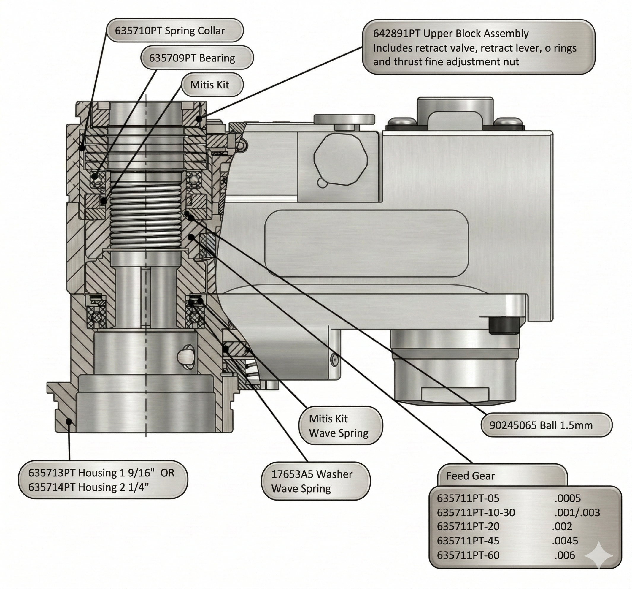
635711PT-05 | Gear, Spindle Mitis Feed – .0005 IPR |
635711PT-10-30 | Gear, Spindle Mitis Feed – .001/.003 IPR |
635711PT-20 | Gear, Spindle Mitis Feed – .002 IPR |
635711PT-45 | Gear, Spindle Mitis Feed – .0045 IPR |
635711PT-60 | Gear, Spindle Mitis Feed – .006 IPR |

| Part Number | Description |
|---|---|
92050331M5-10KIT | Mitis QB230 N=5, A=0.10 |
92050331M5-15KIT | Mitis QB230 N=5, A=0.15 |
92050331M5-20KIT | Mitis QB230 N=5, A=0.20 |
92050331M5-25KIT | Mitis QB230 N=5, A=0.25 |
92050331M5-30KIT | Mitis QB230 N=5, A=0.30 |
92050331M5-35KIT | Mitis QB230 N=5, A=0.35 |
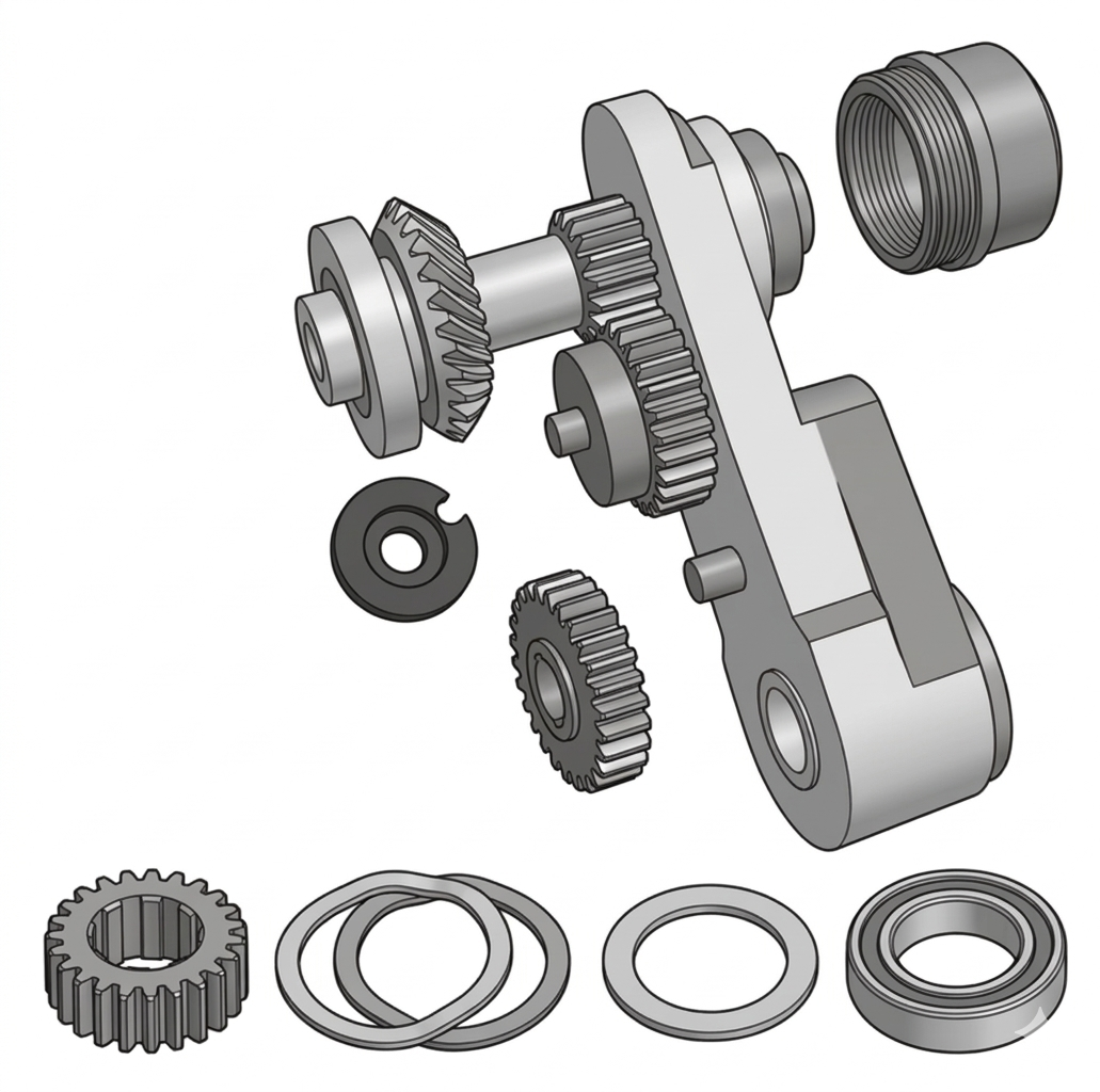
The kit contains parts for both the conversion and for replacement of wear items such as O-rings, snap rings and bearings during the conversion. See legend below.
Replacement Part Part required to replace wear items during conversion. Conversion Part New part required for Mitis conversion.
| Ref | Part Number | Description | Qty | Type |
|---|---|---|---|---|
| SA1 | 635713PT |
Housing, 1 9/16" nose (— OR —) | 1 | Conversion |
| SA1 | 635714PT |
Housing, 1 1/4" nose | 1 | Conversion |
| SA1 | 863009 |
Ring, O | 2 | Replacement |
| SA1 | 864681 |
Spring | 1 | Replacement |
| SA1 | 619017 |
Ring, Retaining | 1 | Replacement |
| 1 | 11-001 | O-Ring 0.038 × 0.116 × 70 Buna-N | 1 | |
| 2 | 617253 | Bearing, Needle | 1 | |
| 3 | 619017 | Ring, Retaining | 2 | |
| 4 | 619019 | Bearing, Ball | 2 | |
| 5 | 619377 | Bearing | 1 | |
| 6 | 812667 | Screw, HSBHC (10-32 UNF × .375) | 2 | |
| 7 | 844301 | Ring, O (same as 1385PT) | 4 | |
| 8 | 844966 | Bearing, Ball | 1 | |
| 9 | 863009 | Ring, O | 3 | |
| 11 | 864471 | Bearing, Ball | 1 | |
| 12 | 867185-M | Valve, Governor | 1 | |
| 13 | 90245065 | Ball, 1.5 mm | 1 | |
| 14 | 17653A5 | Washer, Wave Spring | 1 | |
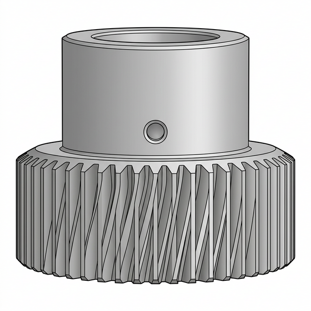
| 15 | 617200A5 | Spindle Drive Gear, Mitis | 1 | Conversion |
| 16 | 635369PT | Bearing, Radial Ball — 25 mm OD, 37 mm Width | 1 | Conversion |
| 17 | 635709PT | Bearing | 1 | Conversion |
| 18 | 635710PT | Spring Collar, Mitis | 1 | Conversion |
| 20 | 642891PT | Upper Block Assembly | 1 | Conversion |
| 21 | 642892PT | Backhead, Mitis | 1 | Conversion |
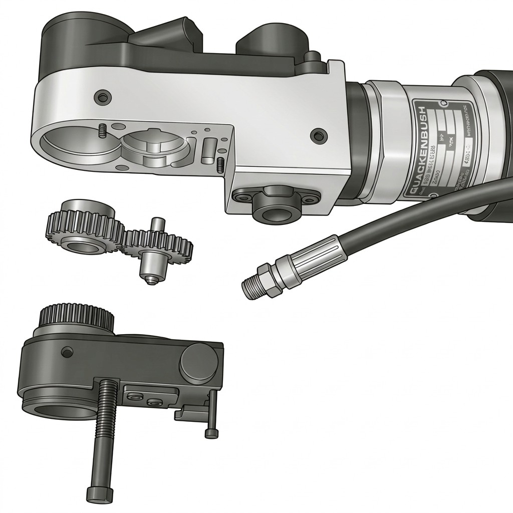
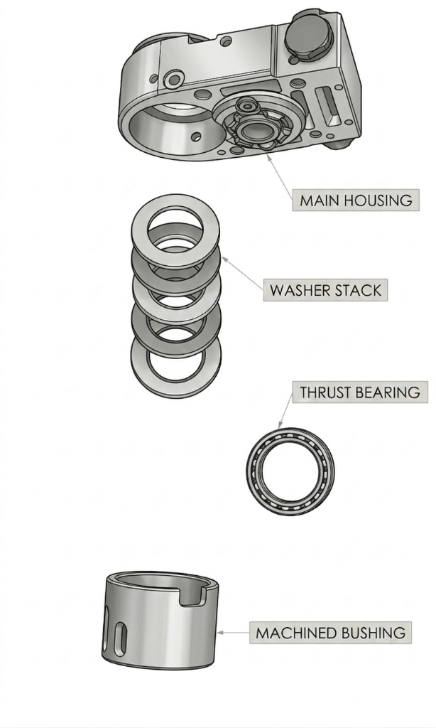
The parts below should be either converted or replaced as noted. Refer to the sectional drawing in Step 5 as well as the exploded view for conversion parts orientation.
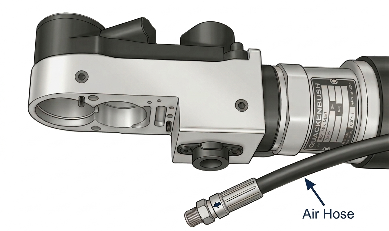
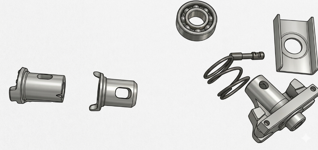
Remove the nose piece, spindle, and spindle guard from the tool per the standard 230 service procedure.
Set these components aside — they will be reinstalled using the new conversion housing at completion.
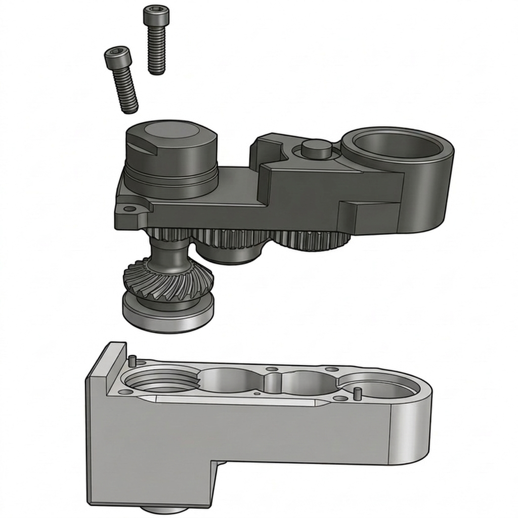
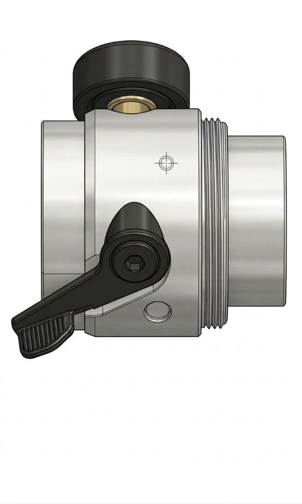
Remove the upper block assembly from the gearhead housing.
Note the orientation of all internal components before removal for reference during reassembly.
Separate the gearhead housing from the power unit body.
Keep all fasteners organized for reassembly.

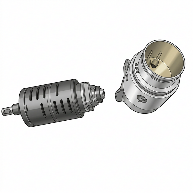
Remove the backhead and motor package from the power unit body.
Keep all components organized and note orientation for reassembly.
Replace the existing backhead with the new Mitis backhead (642892PT).
Ensure all O-rings and seals are properly seated. The new Mitis backhead provides the pneumatic routing required for Mitis clutch operation.
The following recommendations are initial guidelines and should be adapted according to tool utilization.
* Recommended Service Interval is based on 3 possible factors — Calendar Time, Run Time or Run Cycles. The number achieved first should be used to set the maintenance schedule.
** Alternatively: Before or After Each Shift
For additional information or guidance please contact your local Corvaer representative at corvaer.com.
Use the table below to determine service cycle intervals based on your feed rate setting:
| IPR | mm/rev | Stroke (inches) | Stroke (mm) | Recommended Cycles (C) |
|---|---|---|---|---|
| 0.001 | 0.03 | 1 | 25.4 | 333 |
| 0.002 | 0.05 | 1 | 25.4 | 667 |
| 0.003 | 0.08 | 1 | 25.4 | 1,000 |
| 0.004 | 0.10 | 1 | 25.4 | 1,333 |
| 0.005 | 0.13 | 1 | 25.4 | 1,667 |
| 0.006 | 0.15 | 1 | 25.4 | 2,000 |
| 0.007 | 0.18 | 1 | 25.4 | 2,333 |
| 0.008 | 0.20 | 1 | 25.4 | 2,667 |
| 0.009 | 0.23 | 1 | 25.4 | 3,000 |
| 0.010 | 0.25 | 1 | 25.4 | 3,333 |
Applicable Tool Series: 230QR/230QB
| Schedule | Calendar | Run Time | Cycles | Step | Action | Check |
|---|---|---|---|---|---|---|
| W1 Daily** |
Daily | — | — | 1 | Ensure tool is cleaned — all chips/debris removed | |
| 2 | Visually Inspect air supply hose, all pneumatic connections | |||||
| 3 | Inspect airline filter, regulator and lubricator for proper lubrication | |||||
| 4 | Check Air Supply Pressure (90psi dynamic) | |||||
| 5 | Check spindle stop nuts are securely mounted | |||||
| 6 | Check all guards are fitted | |||||
| 7 | Check the tool for excessive vibration/unusual noise | |||||
| 8 | Visual inspect all external components — Especially indexer if fitted — for wear | |||||
| 9 | Inspect the cutter for cracks or damage | |||||
| 10 | Make sure lock screws and drill bushing are securely mounted. | |||||
| 11 | Check Tool Function — Motor Start/Stop/Manual Retract/Automatic Retract | |||||
| 12 | Perform test drill before each shift to ensure correct cutter guide clearance with bushing — replace bushing if clearance is excessive resulting in incorrect hole specification. It is recommended for reaming/countersinking the maximum gap of 1.3 times (1.5 in drilling) of initial maximum gap (generally H7/g6) by design between the spindle and bushing. | |||||
| 13 | Inspect the air supply hose for damage. | |||||
| 14 | Make sure the air inlet connection is securely tightened. | |||||
| 15 | Make sure all tool fasteners are properly tightened. | |||||
| 16 | Check for External Air Leaks — Replace O Rings as necessary | |||||
| 17 | Inspect Fluid Inducer End Seal/Tube for wear/leaks — replace if necessary | |||||
| 18 | Check operation of Lubricator if fitted | |||||
| WS Per Use |
Per Use | — | See Mitis Grease Schedule | 19 | Apply grease to Mitis if fitted — see Mitis Grease schedule | |
| W2 | 3 Months | 80 hrs | 4,000 | 20 | Check Motor Speed — If Low Clean Inlet Screen and Clean or Change Muffler then check/replace Motor Blades as necessary | |
| 21 | 15QB/158QB — The tool should be greased after every 40 hours of operation with a good No. 2 grade Moly grease using a low pressure grease gun | |||||
| 22 | Apply grease to Gear Head and Planetary Gear Box | |||||
| 23 | For QRA (Adaptive) versions Check Sensor Block/Magnets/Adaptive functionality | |||||
| W3 | 6 Months | 160 hrs | 8,000 | 24 | Inspect All O Rings/Seals — Replace as necessary | |
| 25 | 230QR/QB Check thrust overload | |||||
| 26 | Check spindle for wear on threads | |||||
| W4 | 12 Months | 320 hrs | 16,000 | 27 | Inspect All Bearings/Inspect all Gears — Replace if Necessary | |
| 28 | Check All springs — Replace if Necessary |

| # | Maintenance Item | Schedule | OK | Action Reqd |
|---|---|---|---|---|
| 1 | Clean tool — remove all chips/debris | Daily | ||
| 2 | Inspect air hose & all pneumatic connections | Daily | ||
| 3 | Check airline filter, regulator & lubricator | Daily | ||
| 4 | Check air supply pressure (90psi dynamic) | Daily | ||
| 5 | Check spindle stop nuts are securely mounted | Daily | ||
| 6 | Check all guards are fitted | Daily | ||
| 7 | Check for excessive vibration/unusual noise | Daily | ||
| 8 | Inspect external components & indexer (if fitted) for wear | Daily | ||
| 9 | Inspect cutter for cracks or damage | Daily | ||
| 10 | Check lock screws & drill bushing securely mounted | Daily | ||
| 11 | Check tool function (Start/Stop/Manual/Auto Retract) | Daily | ||
| 12 | Test drill — verify cutter guide/bushing clearance (H7/g6) | Daily | ||
| 13 | Check air inlet connection securely tightened; check for external air leaks — replace O rings as necessary | Daily | ||
| 14 | Inspect Fluid Inducer End Seal/Tube; check Lubricator operation (if fitted) | Daily | ||
| 15 | Apply grease to Mitis (per Mitis Grease Schedule) | Per Use | ||
| 16 | Check motor speed — clean inlet screen/muffler; replace motor blades if necessary | 3 Mo. | ||
| 17 | 15QB/158QB — grease every 40 hrs (No. 2 Moly grease) | 3 Mo. | ||
| 18 | Apply grease to Gear Head & Planetary Gear Box | 3 Mo. | ||
| 19 | QRA (Adaptive) — check Sensor Block/Magnets/Adaptive functionality | 3 Mo. | ||
| 20 | Inspect O Rings/Seals — replace as necessary; 230QR/QB check thrust overload; check spindle threads for wear | 6 Mo. | ||
| 21 | Inspect all bearings & gears — replace if necessary | 12 Mo. | ||
| 22 | Check all springs — replace if necessary | 12 Mo. |
For technical support, replacement parts, and authorized service on Quackenbush tools, contact your nearest Corvaer Sales and Service Center. Additional locations may be available at corvaer.com.
