
 Precision Tools for Demanding Applications
Document No. 823081 | Rev. 06/2011
Precision Tools for Demanding Applications
Document No. 823081 | Rev. 06/2011
Read and understand all safety recommendations before operating this tool. Failure to follow these instructions could result in serious injury or death.
Due to the number and variety of tooling applications, the user’s methods engineering departments must consider any hazards that may be associated with each specific application and provide adequate operator protection from inadvertent contact with any moving components.
The clamping and feed mechanisms of self-colleting drill motors are exposed for visibility and can move when the air supply is connected or disconnected. To avoid injury, keep fingers and hands away from these areas when handling or operating this tool.
Some non-ferrous metal chips (or dusts) are combustible. Examples: Aluminum, magnesium, Titanium, and Zirconium. See the material safety data sheets for combustibility of materials drilled. Never collect spark-generating material with combustible material. Examples: Collecting both steel and aluminum or steel and titanium.
Exposure to vibration can injure your hands and arms. Some individuals are susceptible to disorders of the hands and arms when exposed to vibration and/or tasks which involve repetitive work motions. Those individuals predisposed to vasculatory or circulatory problems may be particularly susceptible.
Indicates an imminent hazardous situation which, if not avoided, will result in serious injury or death.
Indicates a potentially hazardous situation which, if not avoided, could result in serious injury or death.
Indicates a potentially hazardous situation which, if not avoided, may result in minor or moderate injury or property damage.
The safety labels found on this tool are an essential part of this product. Labels should not be removed. Labels should be checked periodically for legibility. Replace safety labels when missing or when the information can no longer be read. Replacement labels can be ordered by the part numbers shown below.
| Part No. | Description |
|---|---|
| 624241 | Warning Label — “Keep hands away from clamping and feed mechanisms” |
| 203780 | Warning Label — Vibration exposure and repetitive motion hazards |
| 203245 | Caution Label — Eye protection, hearing protection, respirator, rotating spindle, repetitive work/vibration (included in Backhead 625020) |
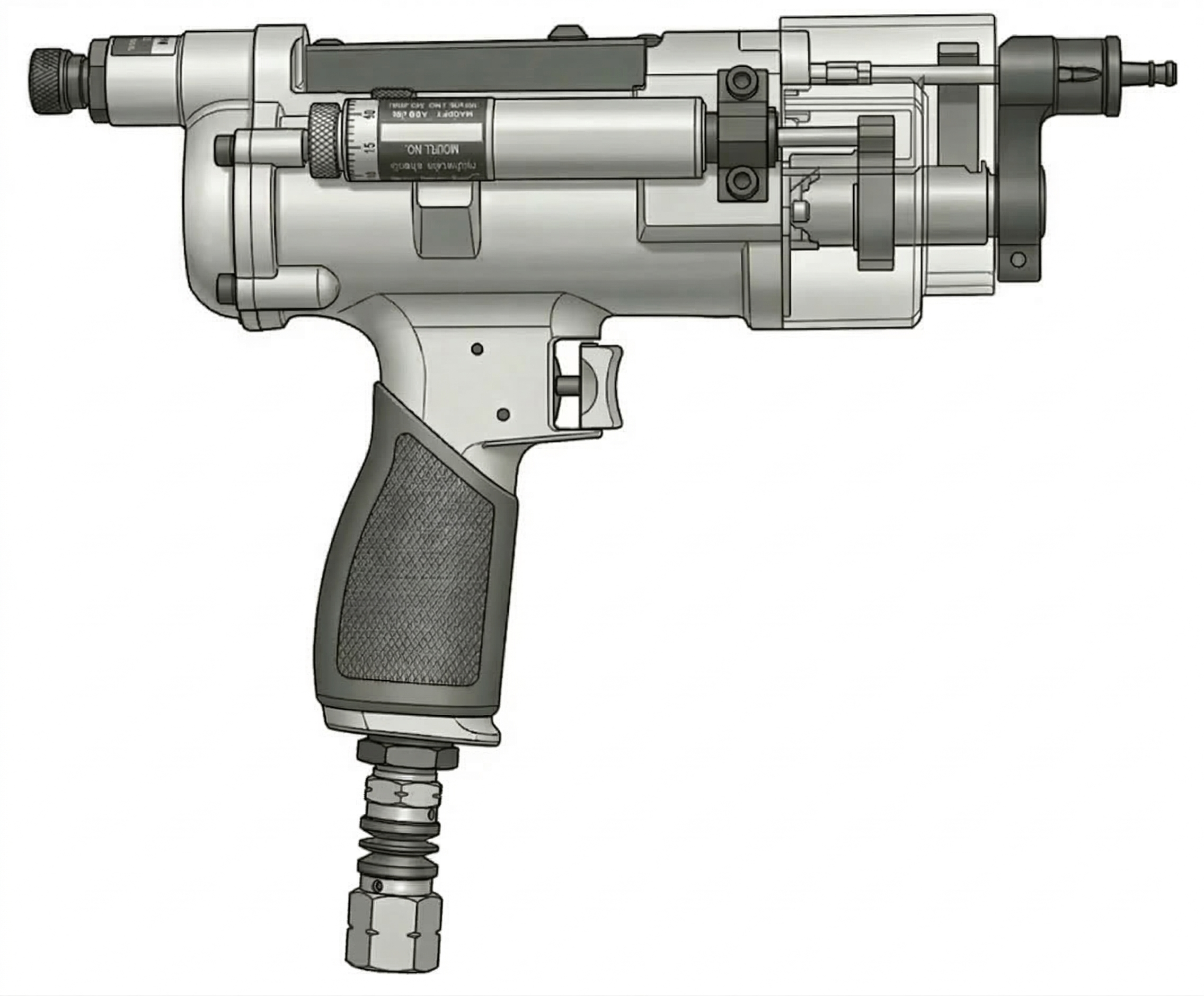
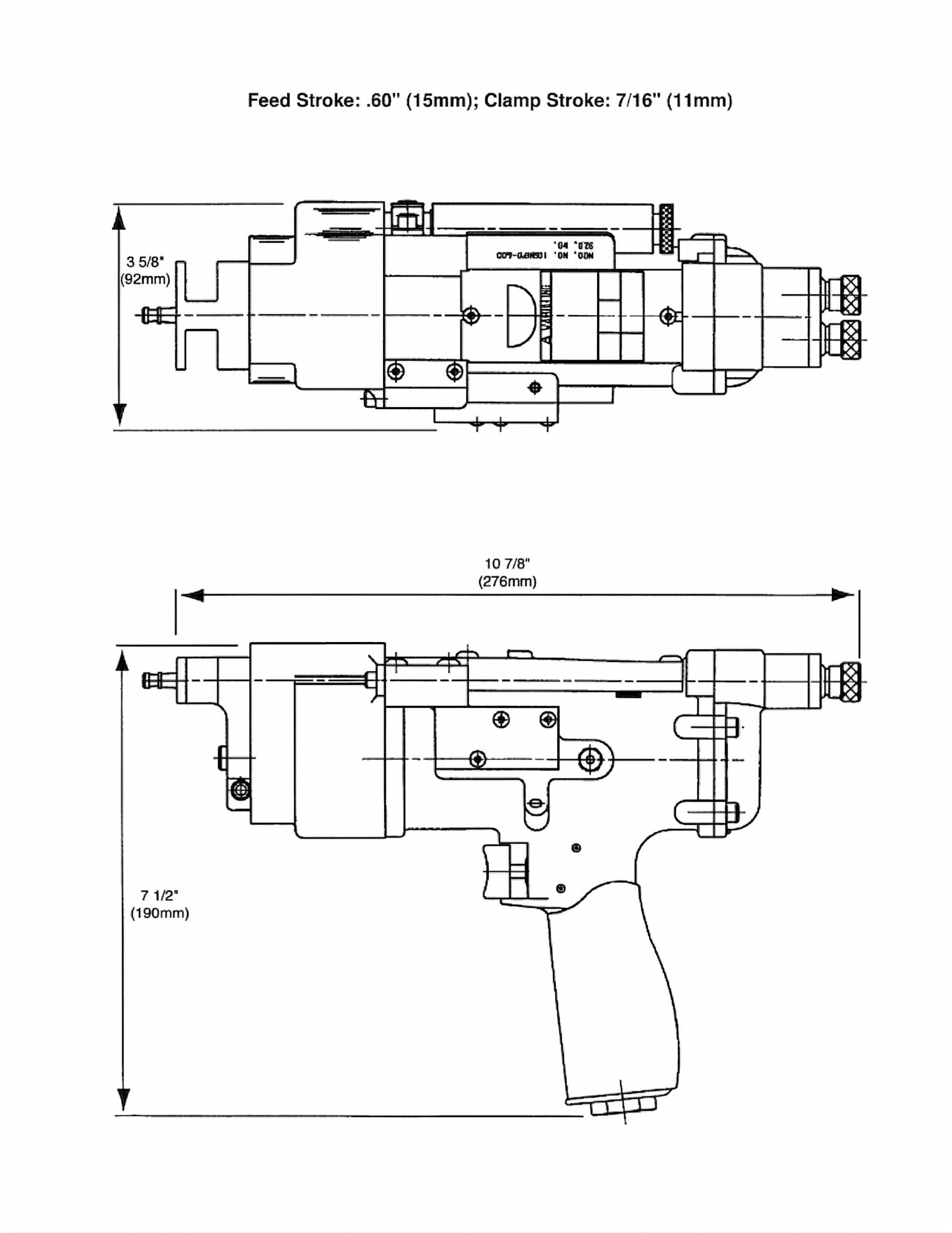
The Q-matic nut plate drill motor has been developed for drilling and countersinking the two holes required for attachment of nut plate fasteners. Utilizing an air/hydraulic feed control piston system, an expanding collet grips the work with 240 lbs holding force during the complete drilling and countersinking operation.
Each Q-matic nut plate drill can be used to drill holes for all three types of nut plate fasteners: single wing, double wing, and Mickey Mouse. By simply changing the front bearing support block, lift finger, and pressure foot, one tool can be used for all types of nut plate fasteners. This eliminates the need for a specific tool to drill and countersink the various nut plate configurations.
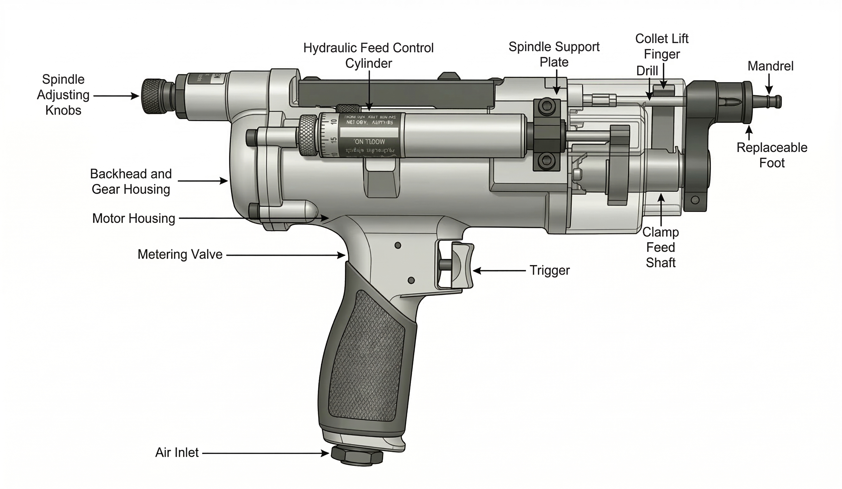
Individual spindle adjustment knobs located at the rear of the tool control countersink depth accuracy within ±0.001″ (0.0254 mm).
Depending upon the hardness of the material being drilled, drilling cycle time can be adjusted from 1.5 seconds to 34 seconds by means of an externally mounted feed control valve.
The Q-matic nut plate drill is available in two geared speed models: 600 RPM and 6,000 RPM. An adjustable throttle control valve located in the handle enables the tool spindle speed to be reduced as much as 50%, allowing the tool RPM to be matched to the material being drilled for optimum drill bit life.
An optional externally mounted pneumatic booster pump is available for use on the 600 RPM models. This pump increases both thrust and clamping force by as much as two and one-half times.
The Q-matic nut plate drill motor is shipped from the factory equipped to the customer’s specifications: spindle RPM, nut plate styles, drill spindle spacing, and optional booster pump (if needed). Collets and mandrels can be supplied for customers with start-up nut plate drilling applications.
After unpacking, examine the customer-specified equipment on the Q-matic tool to verify the style and size of components.
Attach the air line to the 1/4″ NPT inlet bushing. 1/4″ quick disconnect plugs are the minimum recommended size for standard units and 3/8″ quick disconnect fittings are the minimum recommended size for units with booster pumps. The recommended air hose size is 3/8″ inside diameter equipped with an in-line filter and lubricator.
With the air line attached, pull the trigger to start the tool and allow it to run through a full cycle with drills in the fully extended position. When the trigger is released, drills return to the original position and the collet extends to the open position.
To adjust depth of countersink, turn the spindle adjusting knobs at the rear of the tool to the appropriate depth. Turning the knobs counterclockwise reduces depth; clockwise increases depth.
Testing the tool on a separate piece of material will ensure that the tool is operating properly and that the countersink depth has been accurately set.
Use a conventional drill to drill the pilot hole in the material. The size of this pilot hole should match the diameter of the collet and mandrel selected for the tool.
Insert the collet in the pilot hole while holding the pressure foot firmly against the surface to be drilled, and actuate the trigger. The mandrel will retract and clamp the tool firmly against the work while the two drills begin feeding into the material.
The drilling cycle is complete when the drills have reached the maximum pre-set depth. Releasing the trigger will cause the drills to retract and the collet to release. The tool is now ready to begin another cycle.
Step 1
Remove Drills
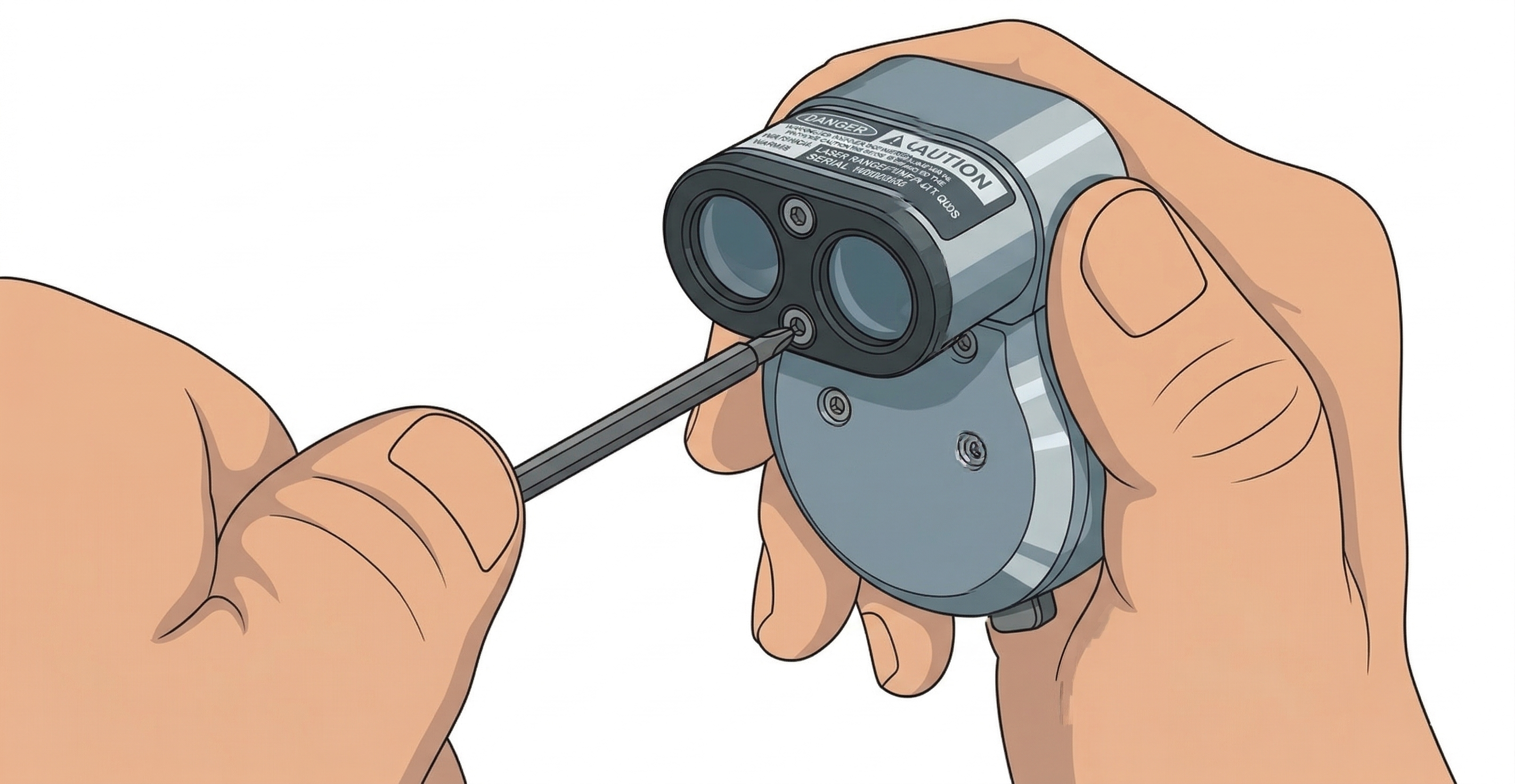
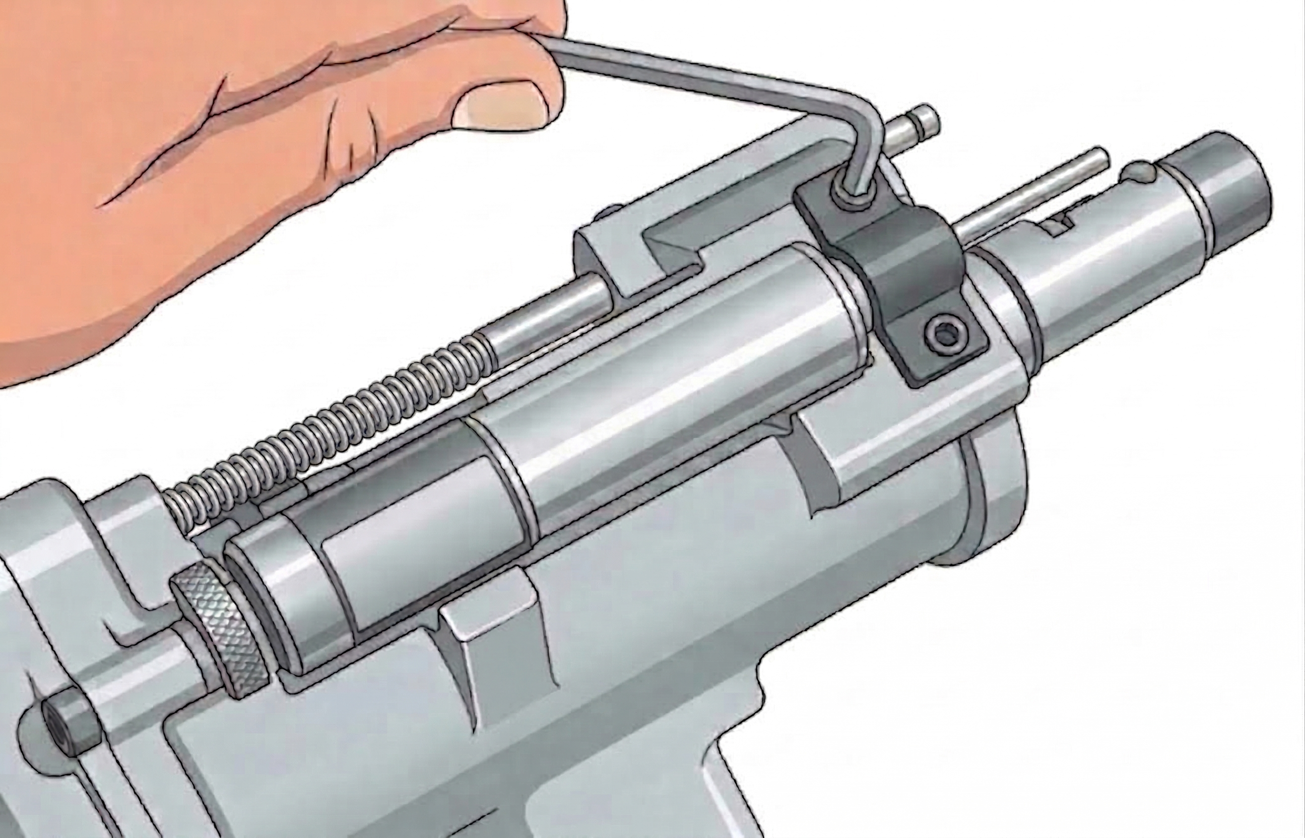
Remove the drills from the spindles by holding each spindle with an adjustable wrench on the flats. Insert a pin-type tool into the hole provided in the drill shank and turn the drill counterclockwise. (Drills are right-hand threads.)
Step 2
Remove Mandrel & Collet Spring
Remove the mandrel from the lift finger by turning counterclockwise, then remove the collet spring.
Step 3
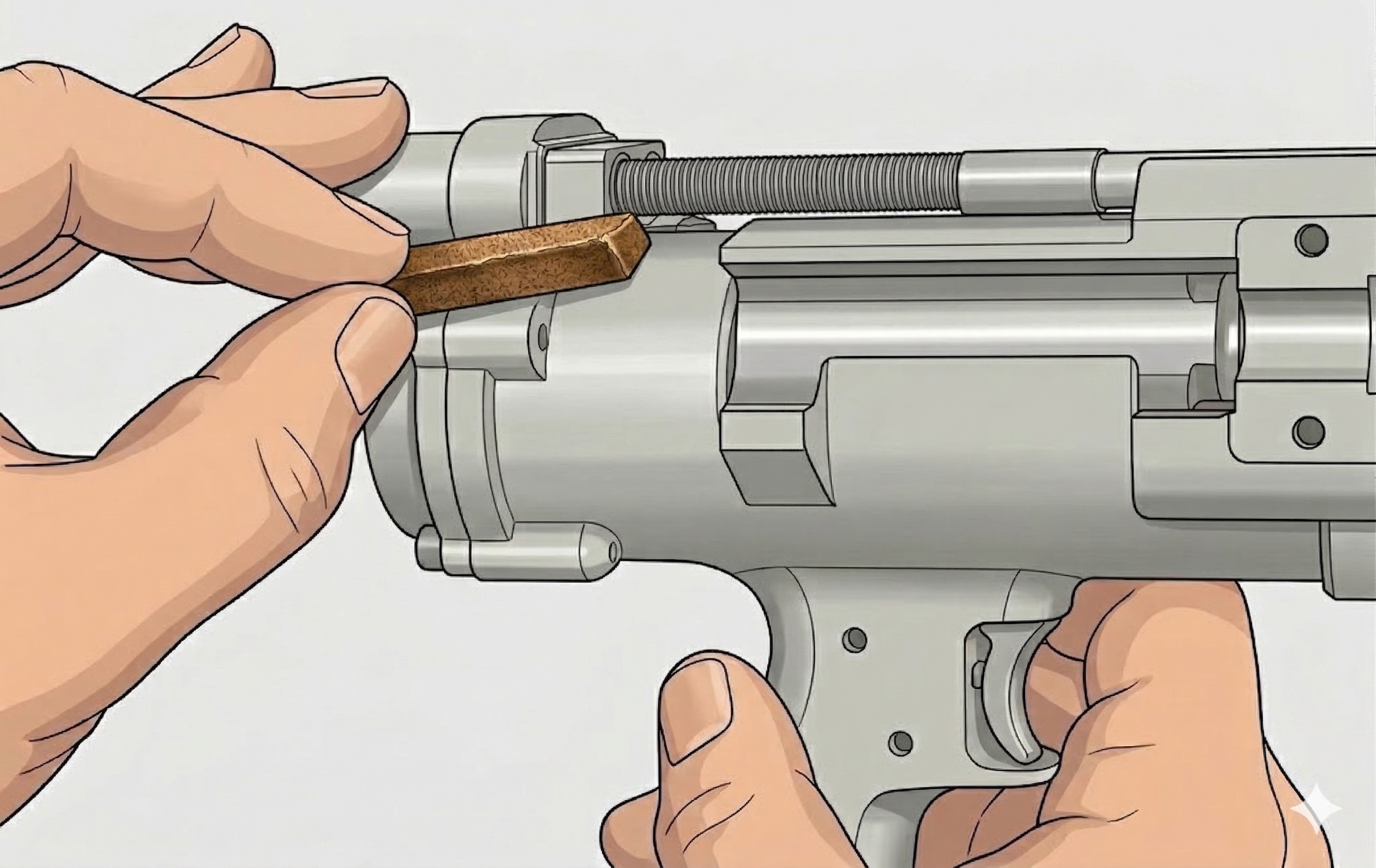
Remove Pressure Foot
Remove the pressure foot by loosening the clamp screw, then unscrew the pressure foot attachment from the collet closing piston rod.
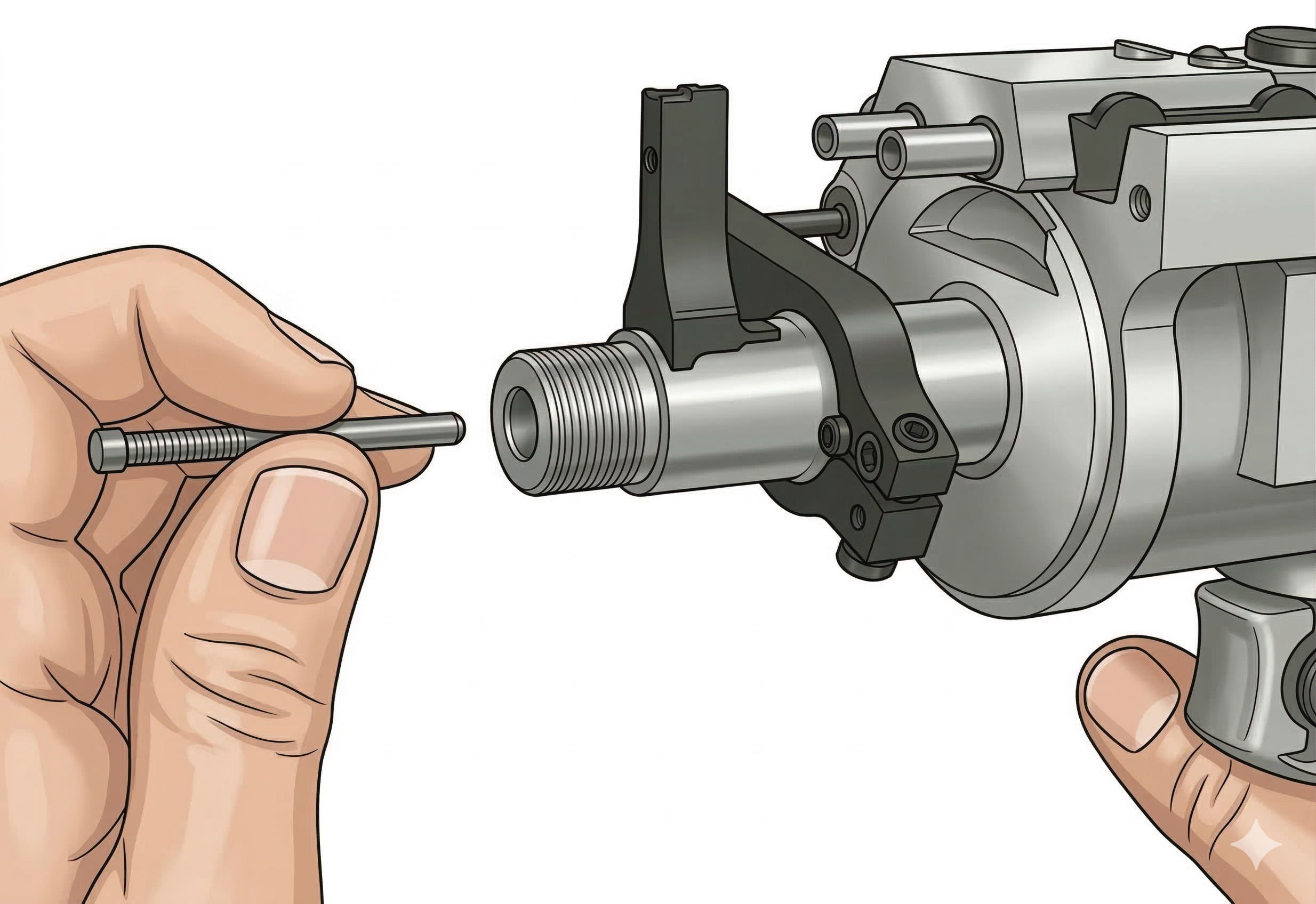
Step 4
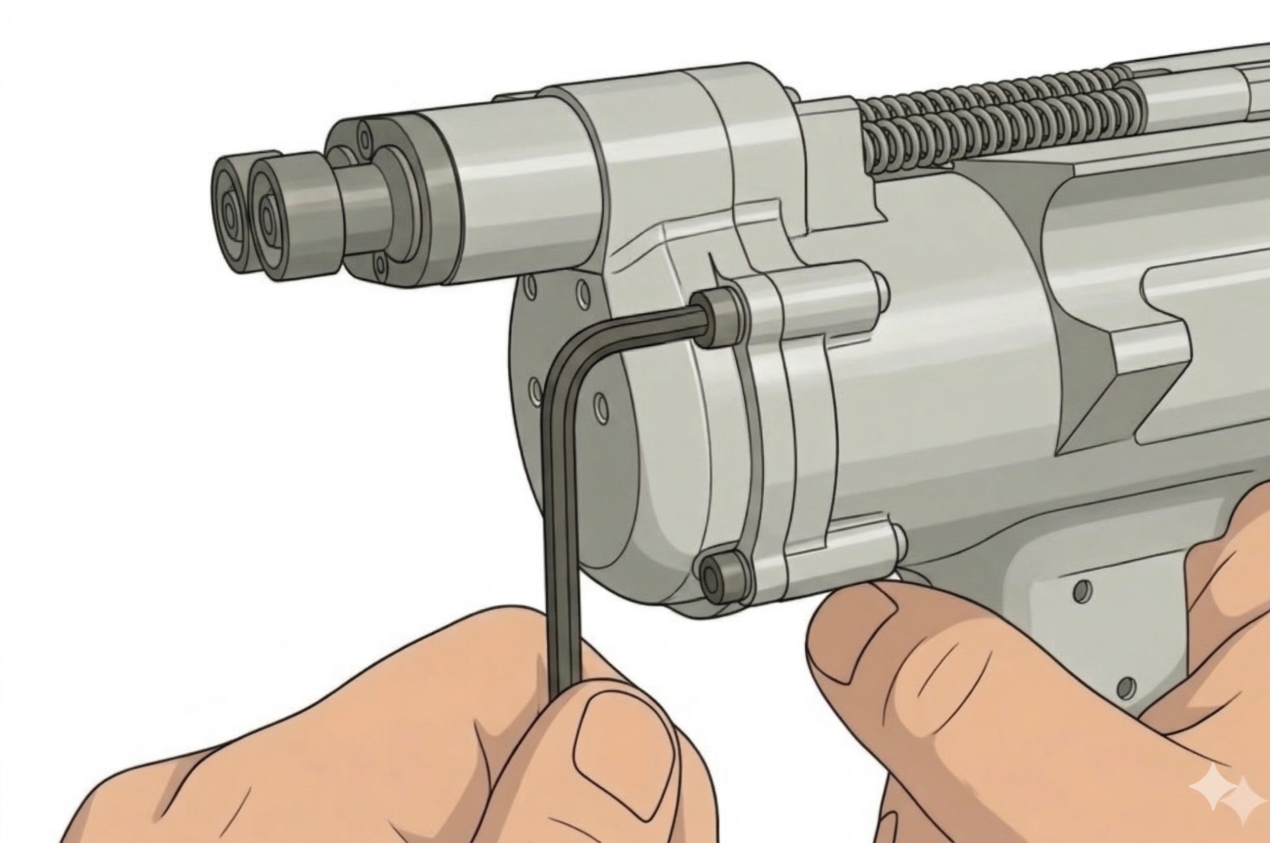
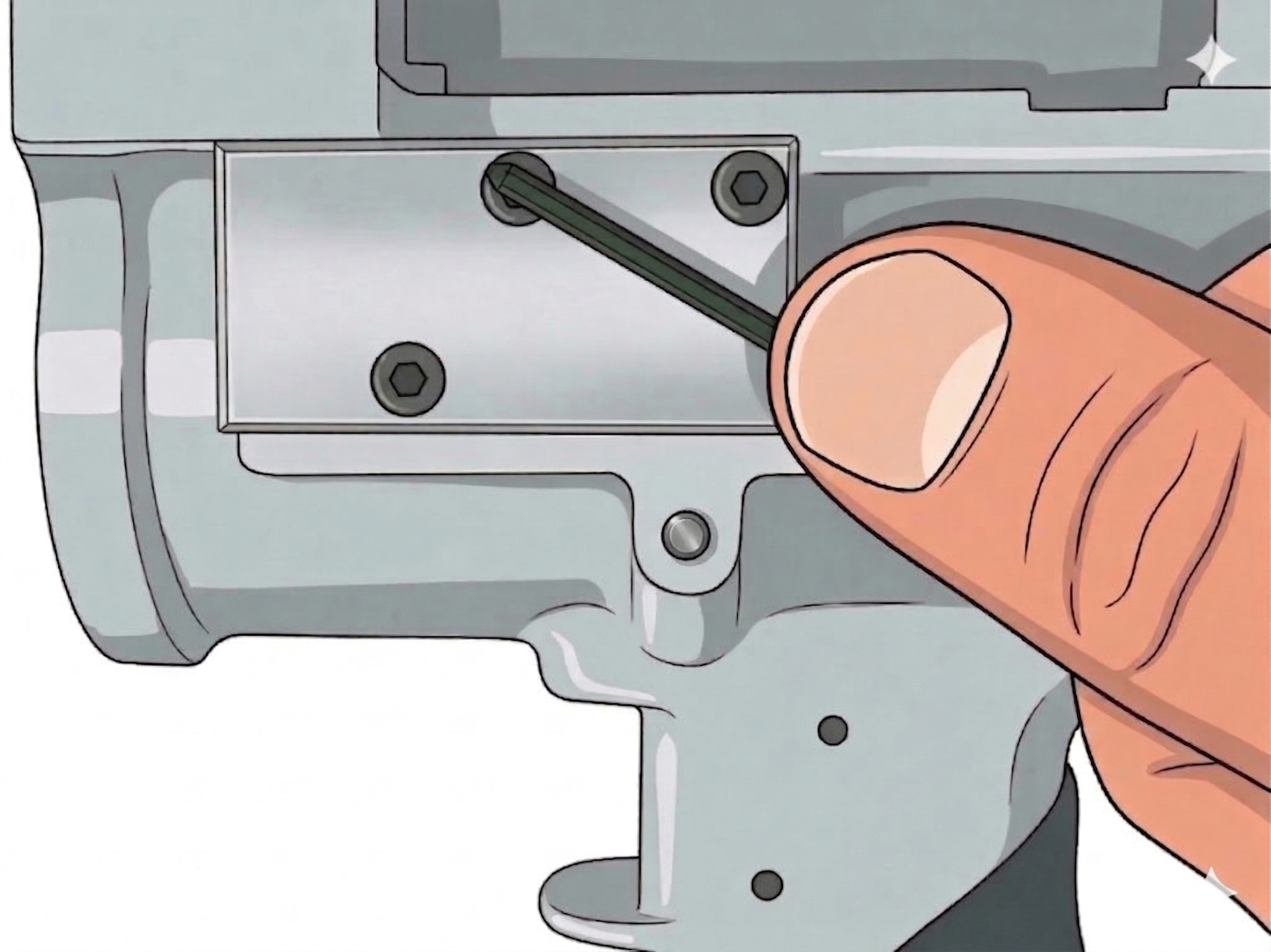
Remove Lift Finger Screw
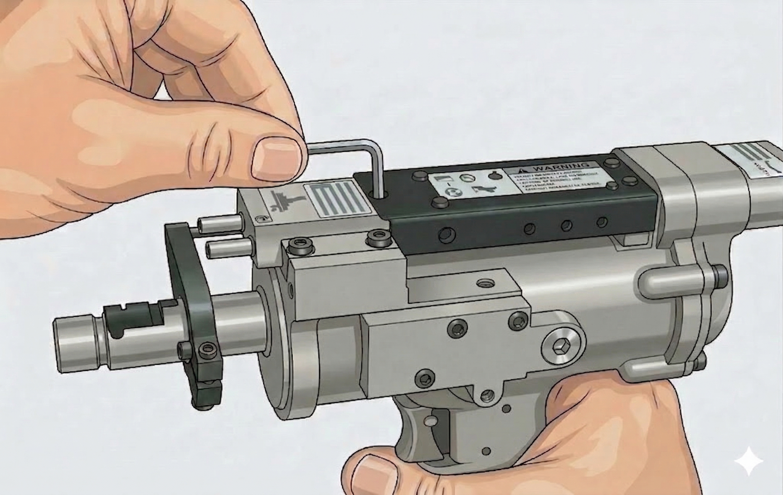
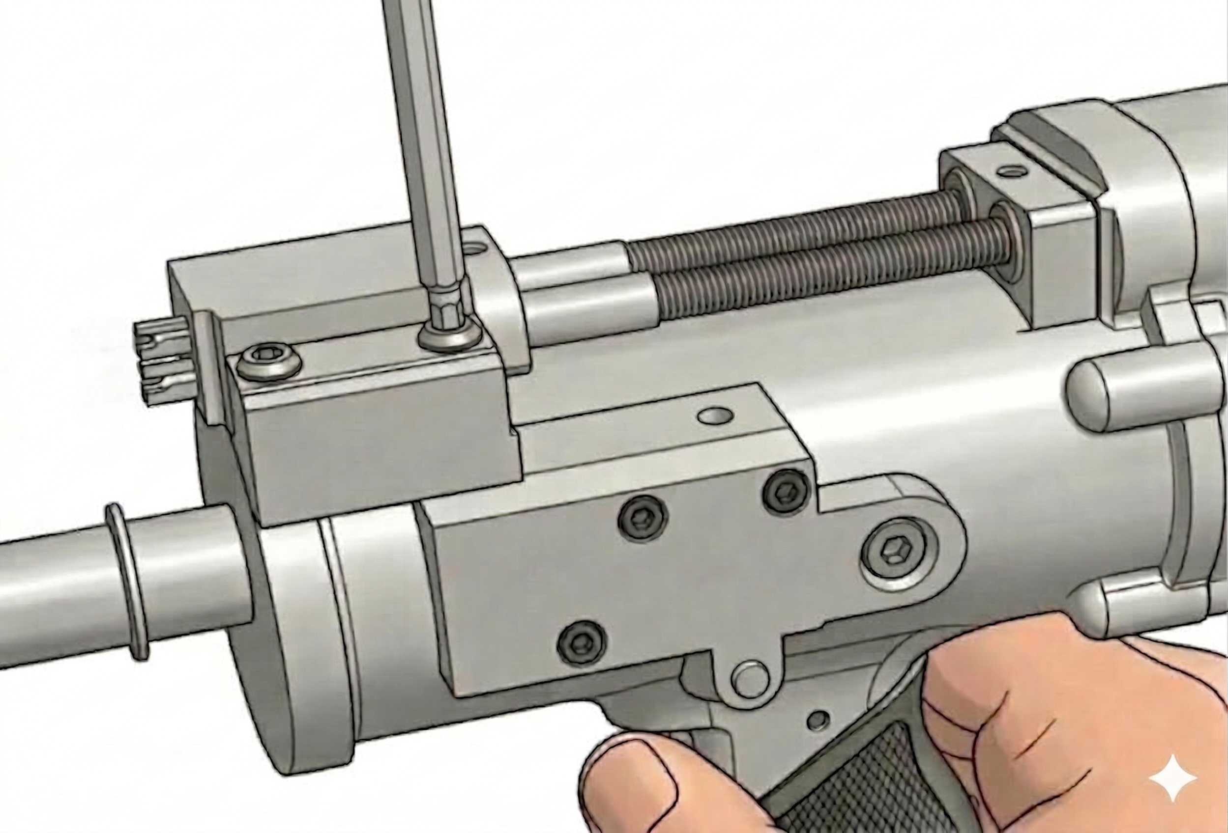
Remove socket head cap screw 622060 from the clamp feed shaft with a hex wrench.
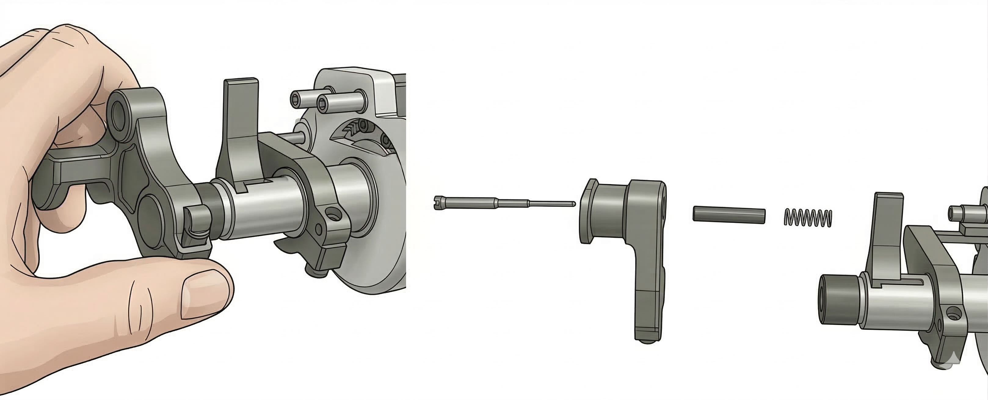
The following steps for removing the retract lift finger can only be used if the tool has not been disassembled in any other way. If the backhead has been removed, this method cannot be used.
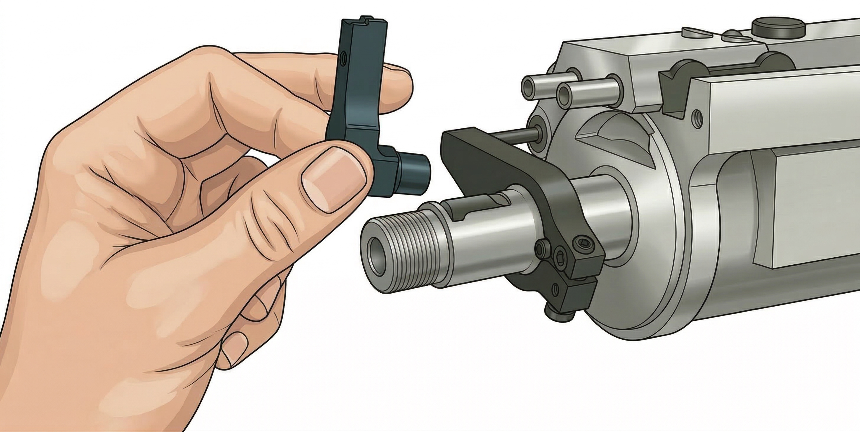
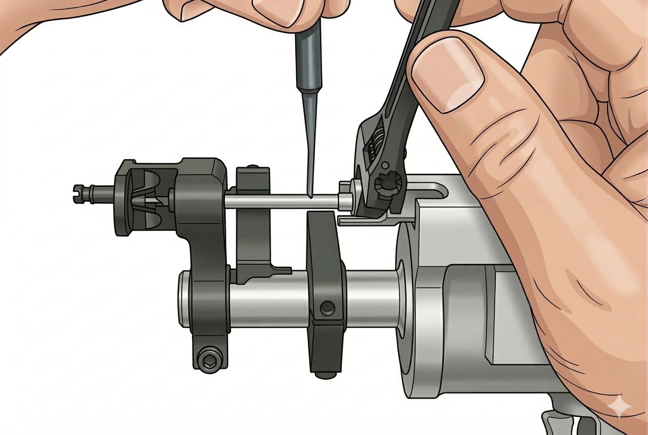
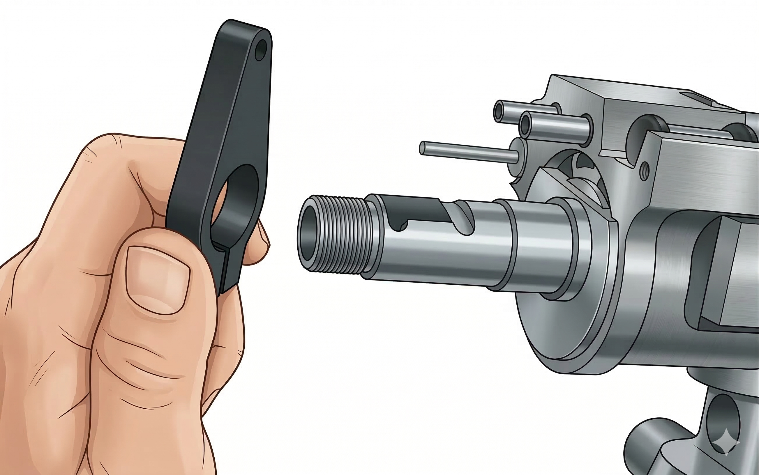
Step 5
Remove Lift Finger
Remove the retract lift finger by attaching the air line to the tool and pulling the trigger. At this time the retract lift finger can be lifted up and forward out of the tool. Disconnect air from the tool again to proceed with disassembly.
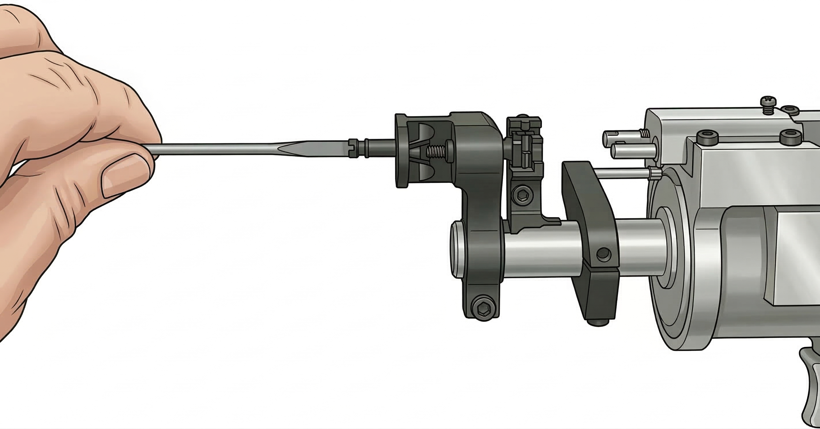
Step 6
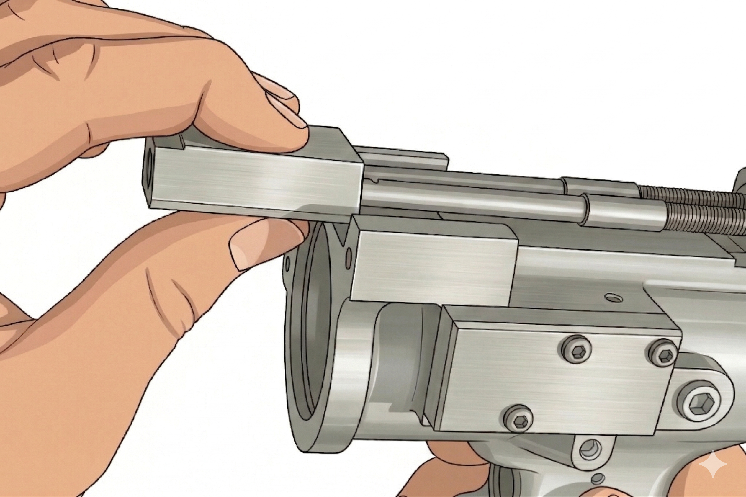
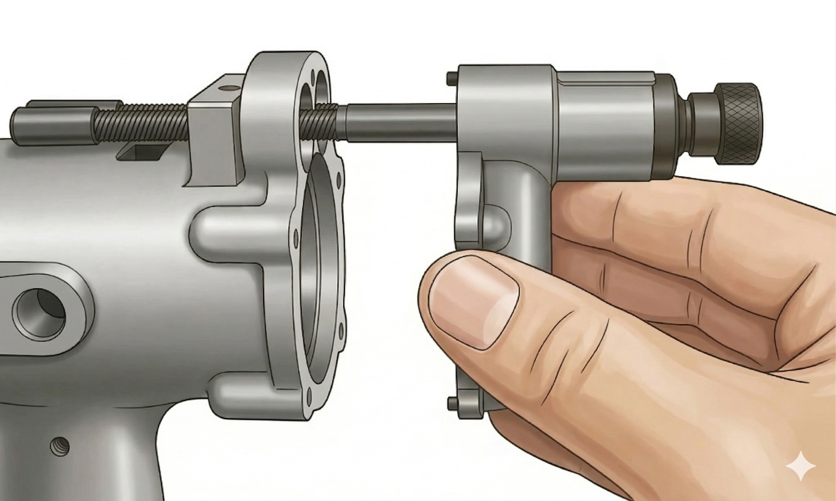
Remove Feed Adjustment Foot
Remove feed adjustment foot 625031 by removing lift finger screw 833106 and sliding the adjustment foot off the clamp feed shaft.
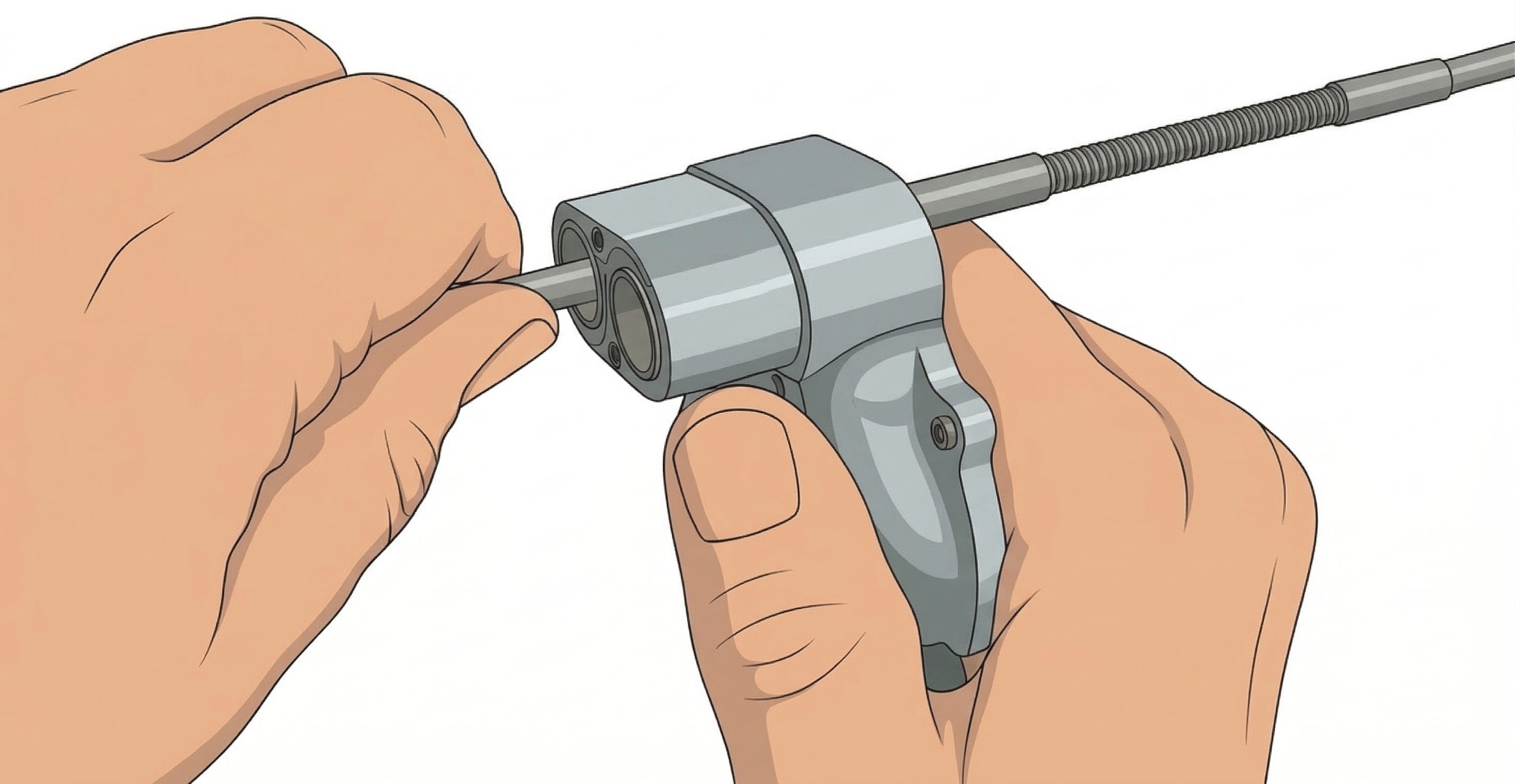
Step 1
Remove Spindle Cover
Remove button head screws 619684 and 622063 from front and rear of spindle cover 625063.
Step 2
Remove Support Wedge
Remove two button head cap screws 622059 from support wedge 622082.
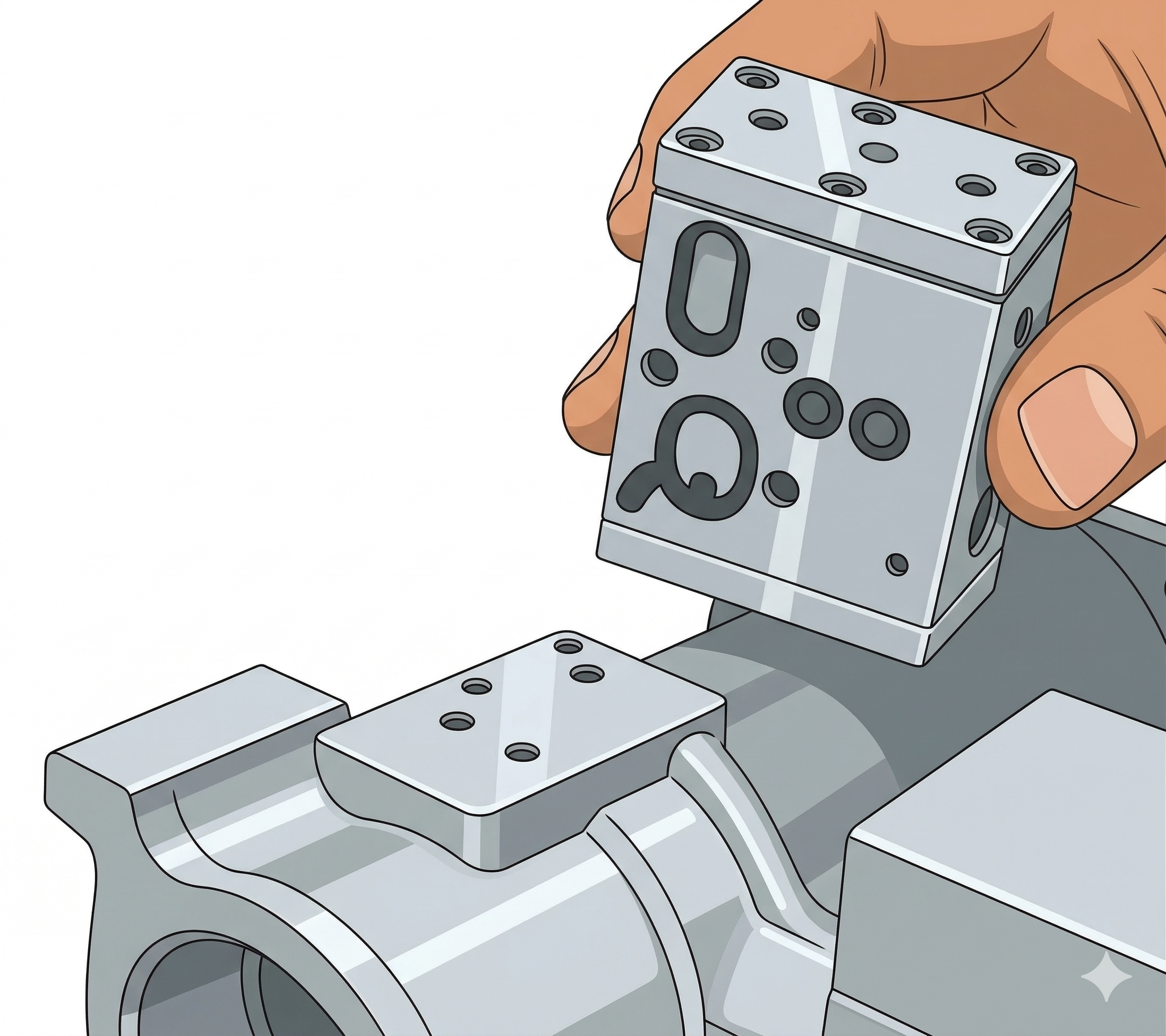
Step 3
Remove Support Plate
Remove the support plate from the spindles.
Step 4
Remove Muffler Pad
Remove the muffler pad 625052.
Step 5
Remove Backhead Bolts
Remove four socket head cap screws 847688 from backhead 625020.
Step 6
Remove Backhead & Spindle Assemblies
Remove the backhead and spindle assemblies from the motor housing.
Note: Four idler gears are held in position by idler gear shafts in the backhead, and are retained by the gear plate 622101.
Step 7
Remove Adjustment Knob Retainers
Remove retainer ring 625467 to release spindle adjustment nut 625027, adjustment knob spring 622140, and adjustment knob 625023.
Step 8
Remove Spindle Adjustment Screws
Remove the spindle adjustment screw 625026 by screwing the spindle clockwise through the backhead assembly 625020.
Step 9
Remove Spindle Adjustment Plate
Remove two socket head cap screws 622774 from spindle adjustment plate 625019 and remove plate.
Step 10
Remove Bearing Retainer Rings
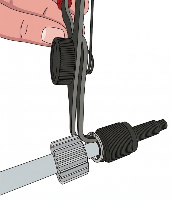
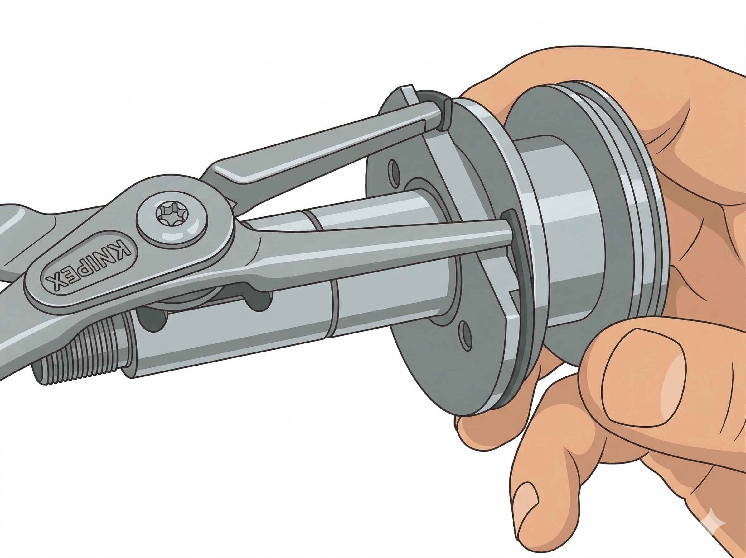
Remove retainer ring 623685 with bent internal pliers. Pull off spindle adjustment screw 625026 to expose bearings.
Step 11
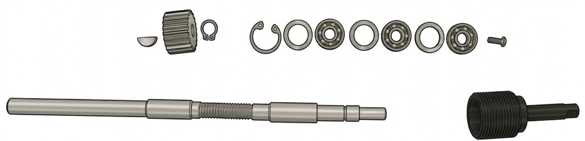
Remove Spindle Bearings & Gear
Remove button head screw 625068 to release spindle bearings 863582 and shims. Remove retainer ring 833774 to release spindle gear 622097 and key 622057.
Note: Keep shims organized by spindle for reassembly. Shim spacers: 623765 (.006″ std), 864730 (.001″), 864731 (.002″), 864732 (.005″).
Step 1
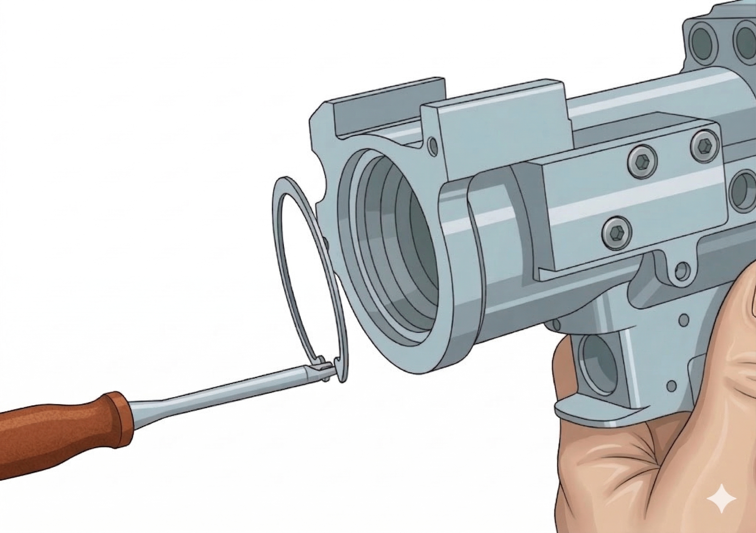
Remove Clamp Feed Shaft
Front enclosure retainer ring 622061 must be compressed with internal pliers and aligned properly to prevent interference with the retainer ring groove in the housing to allow the clamp feed shaft 625030 and front enclosure 625029 to be pulled out.
Note: The O-rings and suction is tight.
Step 2
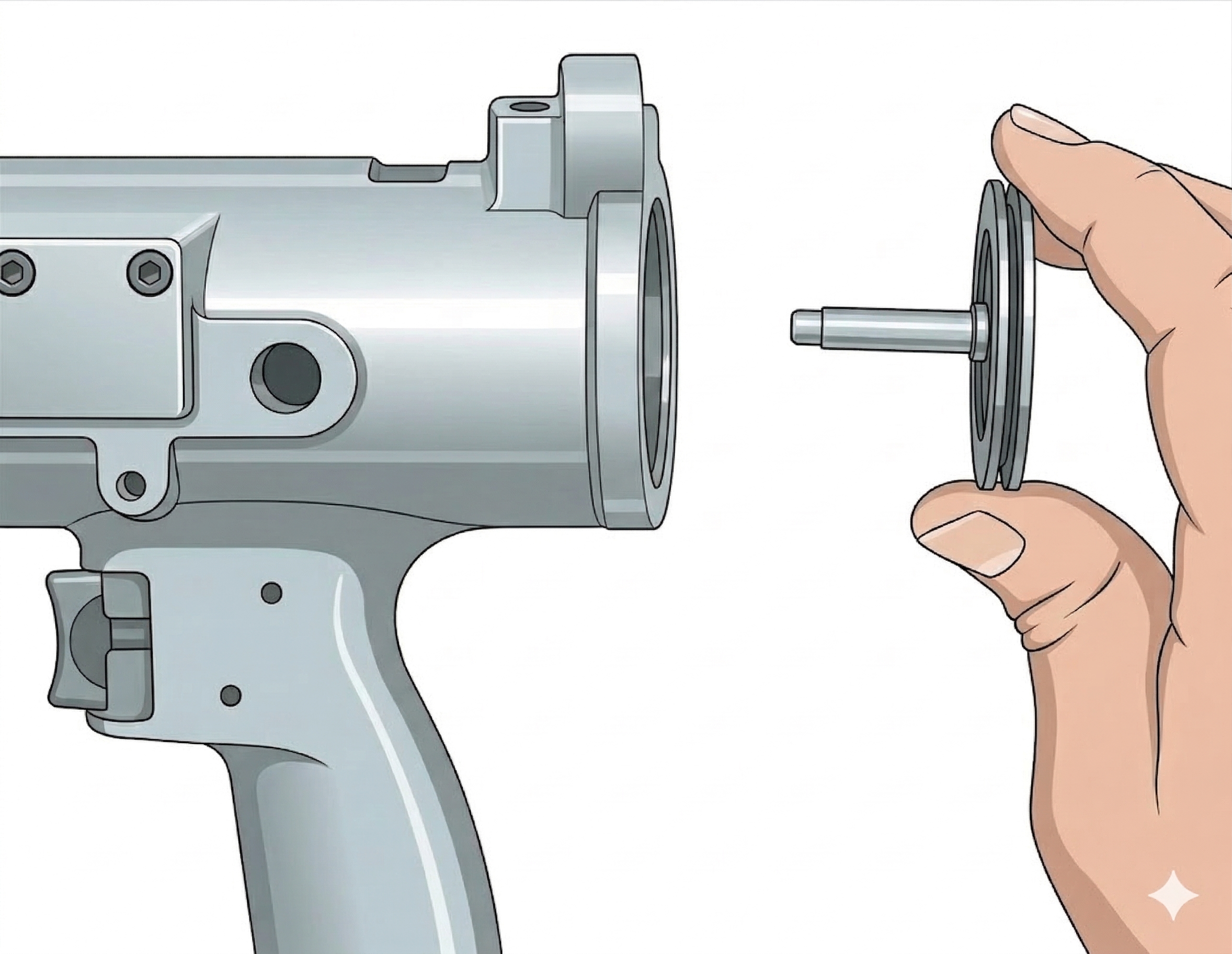
Remove Spiral Ring & Shaft
Remove clamp feed shaft spiral ring 622771 and slide clamp feed shaft 625030 out of front enclosure 625029.
Step 3
Remove Collet Piston
Remove collet piston 625042 from the housing.
Step 4
Remove Collet Piston Spring
Remove the collet piston spring 625033.
Step 1
Remove Gear Components
Remove the pinion gear 625061 (6,000 RPM) or gear pinion spur 622106 (600 RPM), and retainer ring 613126 if present. Remove the gear plate spacer 625058 (6,000 RPM only), wavy washer 625872, and gear plate 622101 from housing.
Step 2
Remove Motor
Remove the motor from the housing, noting the orientation of the motor in the housing. Refer to the Motor Assembly diagram (Section 4.3) for motor alignment.
Step 3
Remove Retainer Ring
Remove the rear bearing plate support retainer ring 622065.
Step 4
Remove Rear Bearing Plate Support
Remove rear bearing plate support 625045 with a soft-faced mallet.
Step 5
Disassemble Motor
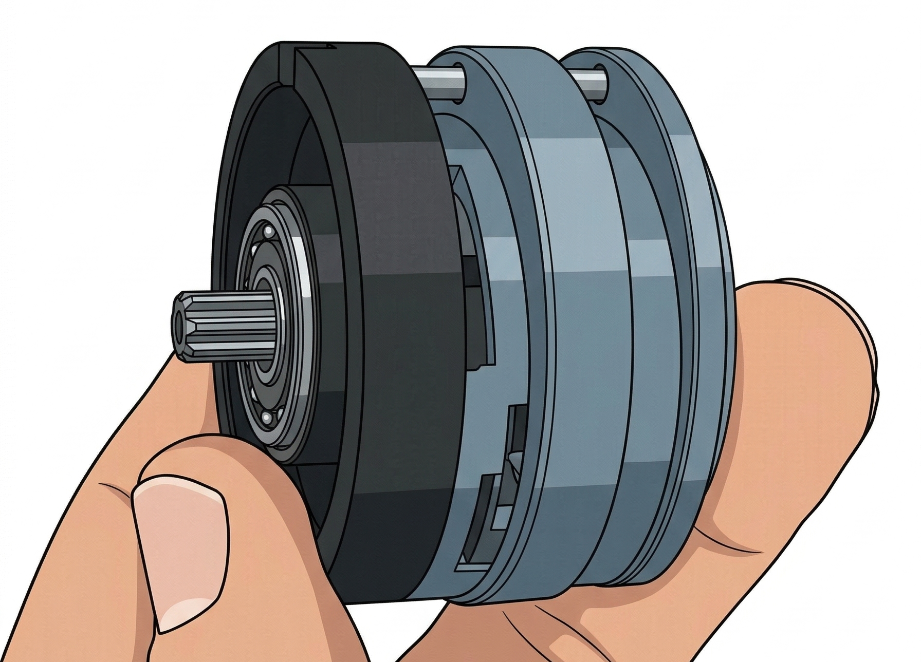
The motor can be disassembled by tapping on the spline shaft of the rotor 625049 with a soft-faced mallet. The rotor can be driven out of the rear bearing plate 625047 with a punch and hammer.
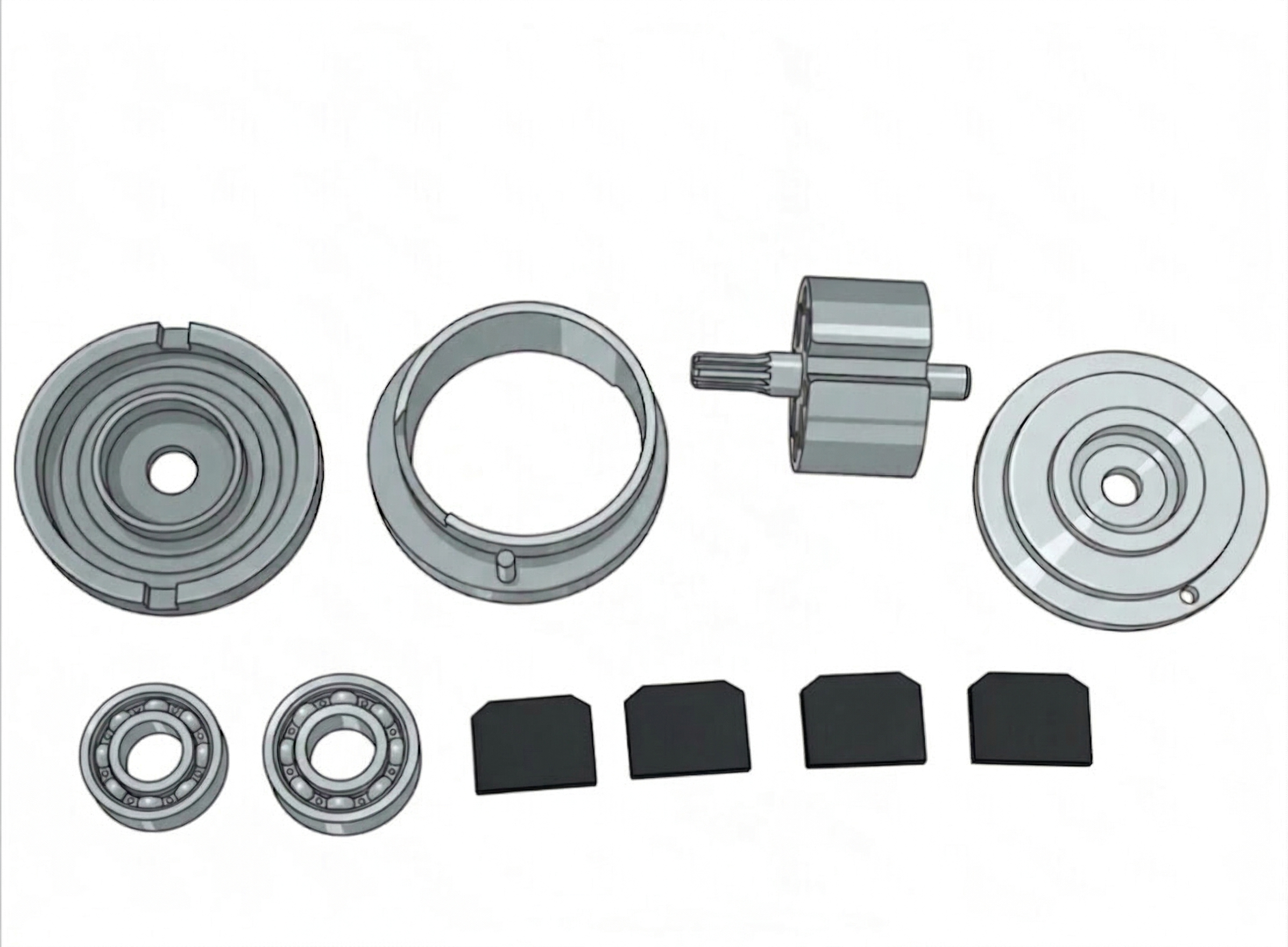
Note: When reassembling the motor, the rear bearing plate should be driven onto the rotor shaft first. Allow about 0.0015″ clearance between the rotor and bearing plate. Refer to the Motor Assembly diagram (Section 4.3) for rotor blade and motor air inlet alignment.
Step 1
Remove Feed Control Piston
Remove the socket head cap screws 883731 and the complete assembly and feed control piston support 625043.
Step 1
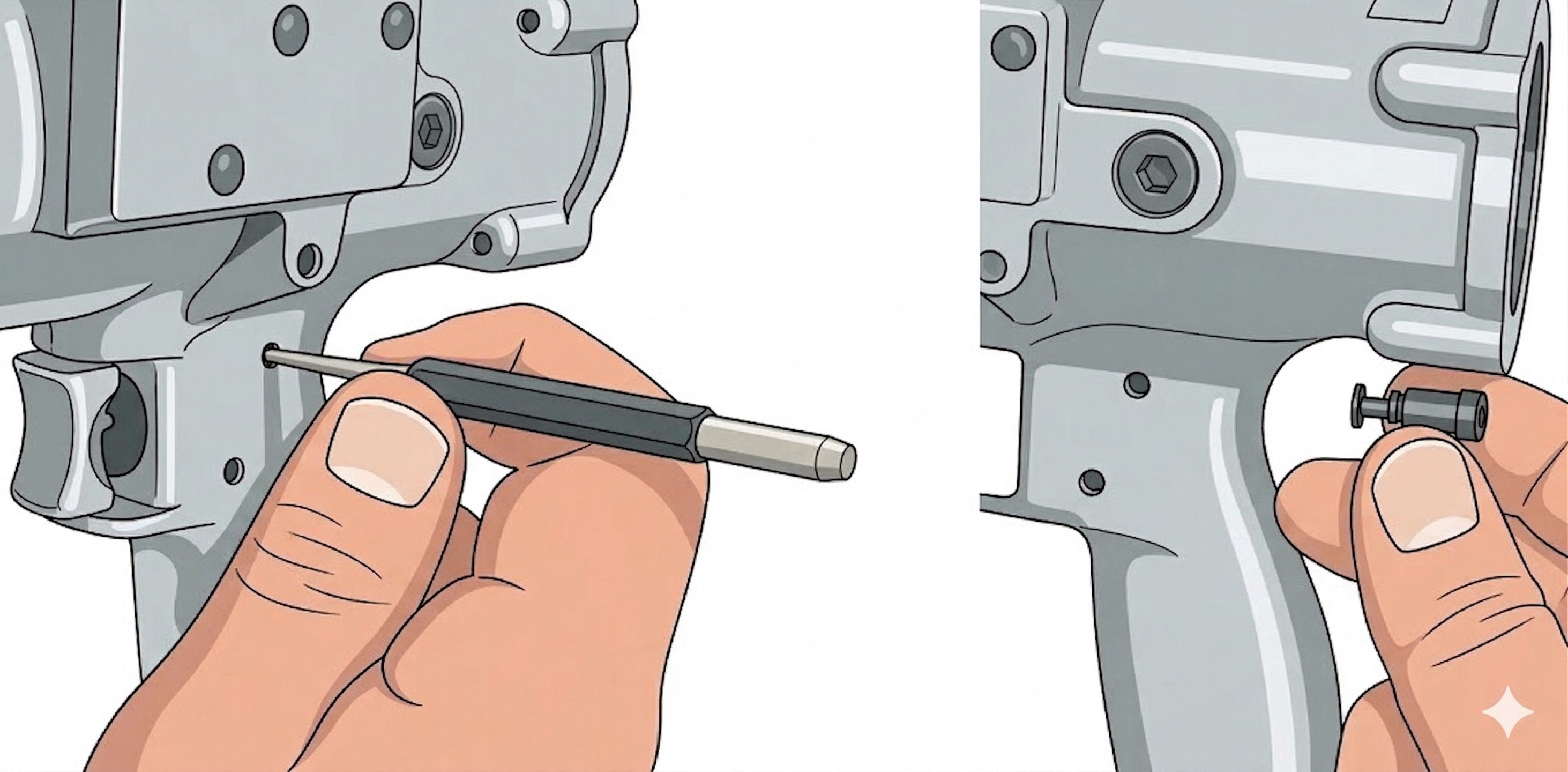
Remove Trigger Assembly
Drive dowel pin 844083 out with a punch and hammer. Pull the complete assembly out of the handle. Remove “O”-ring 869712 to remove trigger 203075 from trigger casing 203083.
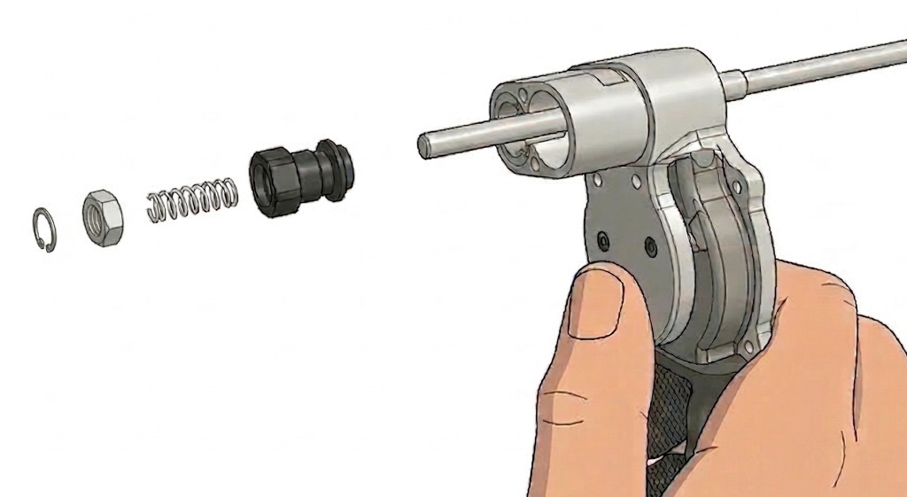
Step 1
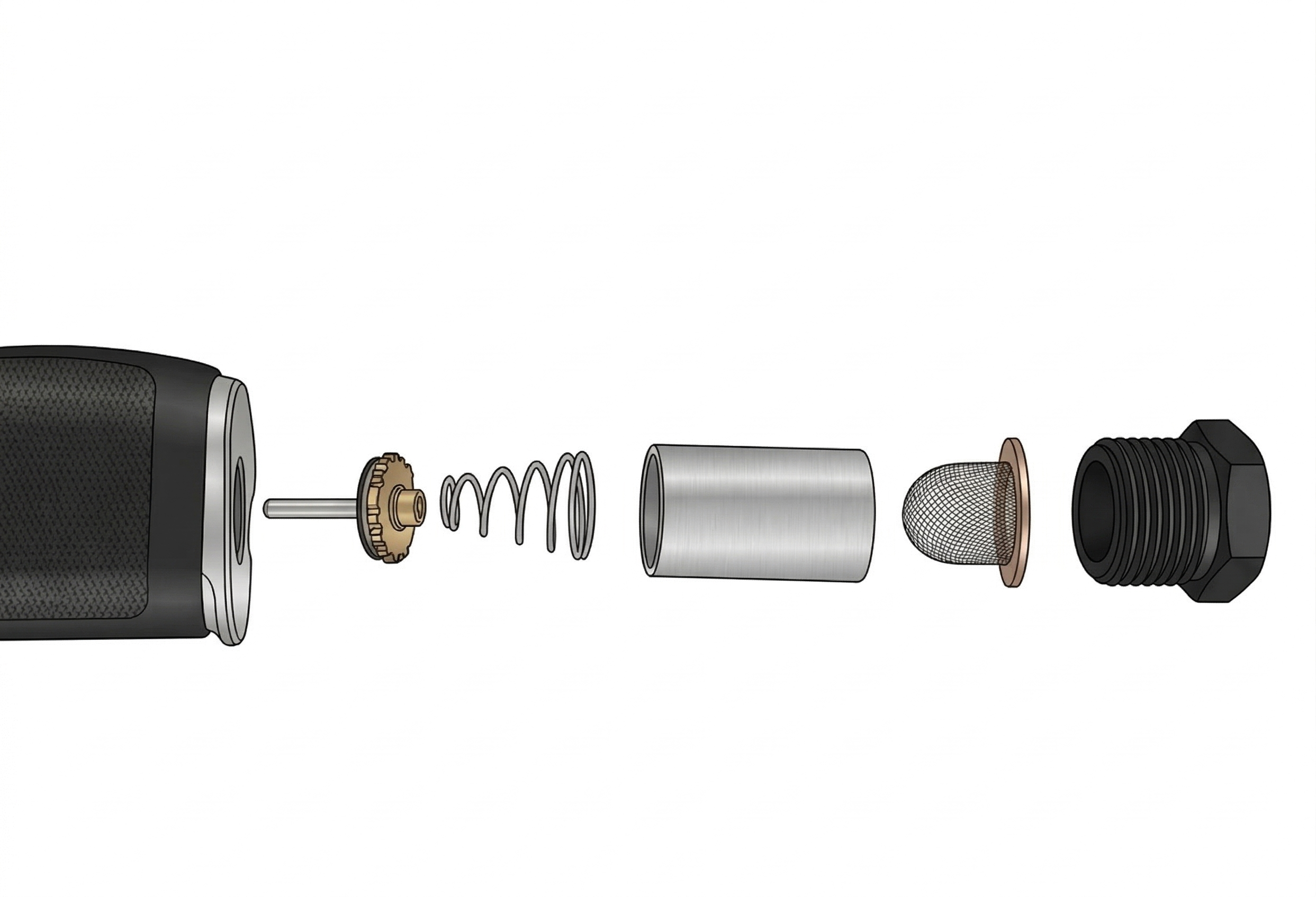
Remove Throttle Valve Assembly
Set the handle in a vertical position and remove inlet bushing 833471, then lift out inlet screen 869548, inlet spacer 625070, throttle valve spring 863072, and throttle valve 625028.
Step 1
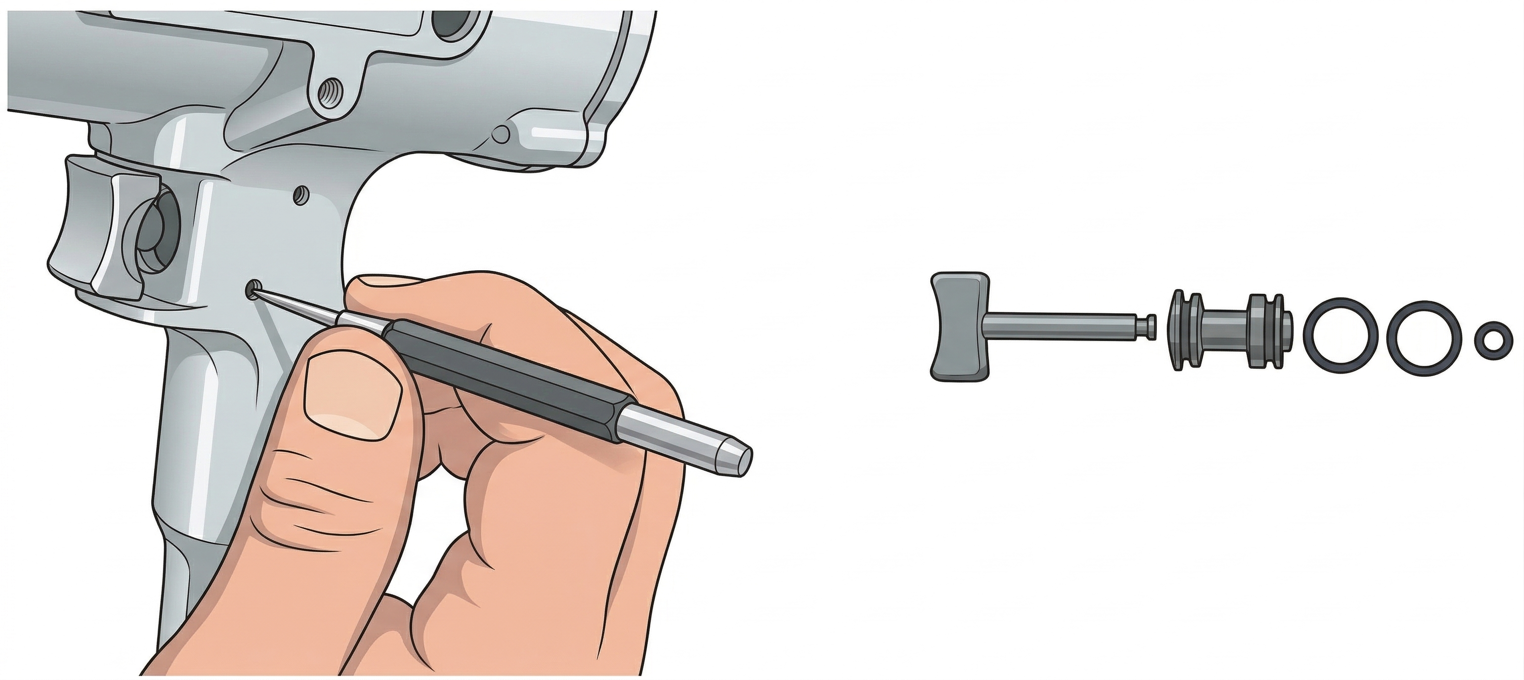
Remove Metering Valve
Drive dowel pin 844083 out with a punch and hammer. With a narrow screwdriver, unscrew metering valve 625071.
The air booster pump is available for 600 RPM models only.
Step 1
Remove Cover Plate
Remove the cover plate 621439 by unscrewing three button head screws 622053.
Step 2
Mount Booster Pump
Mount optional air booster pump assembly 621482 with three socket head cap screws and O-rings supplied with the air booster pump kit.
Note: The booster pump is recommended for use only in the 600 RPM model tool.
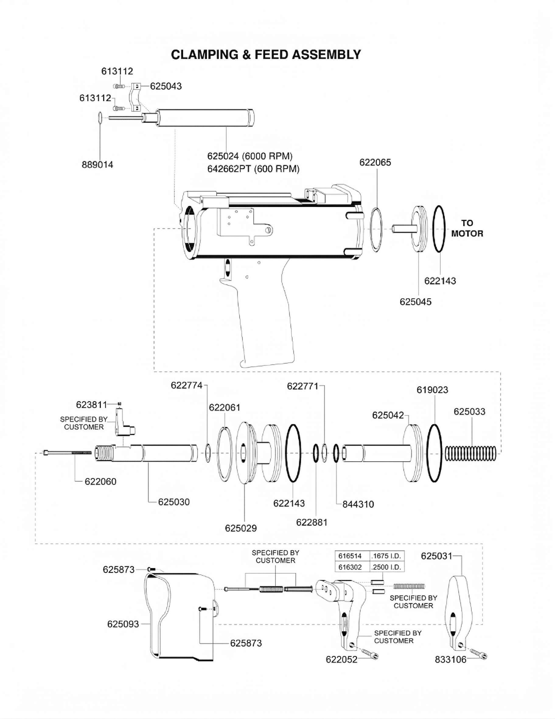
| Model No. | Name of Part | Qty. |
|---|---|---|
| 613112 | Feed Adjustment Support Screw | 2 |
| 616302 | Pressure Foot Bushing .2500 I.D. | 2 |
| 616514 | Pressure Foot Bushing .1875 I.D. | 2 |
| 619023 | “O”-Ring 1-3/4″ x 2″ | 1 |
| 622052 | Pressure Foot Screw (included in Pressure Foot) | 1 |
| 622060 | Lift Finger Screw | 1 |
| 622061 | Front Enclosure Retainer Ring | 1 |
| 622065 | Rear Bearing Plate Support Retainer Ring | 1 |
| 622143 | “O”-Ring 1-13/16″ x 2″ | 2 |
| 622771 | Clamp Feed Shaft Spiral Ring | 2 |
| 622881 | “O”-Ring 55/64″ x 1-9/64″ | 1 |
| 623811 | Set Screw (included in Lift Finger) | 1 |
| 625024 | Feed Control Piston | 1 |
| 625029 | Front Enclosure | 1 |
| 625030 | Clamp Feed Shaft | 1 |
| 625031 | Feed Adjustment Foot | 1 |
| 625033 | Collet Piston Spring | 1 |
| 625042 | Collet Piston | 1 |
| 625043 | Feed Control Piston Support | 1 |
| 625045 | Rear Bearing Plate Support | 1 |
| 625093 | Foot Guard | 1 |
| 625873 | Foot Guard Screw | 2 |
| 833106 | Feed Adjustment Foot Screw | 1 |
| 844310 | “O”-Ring 1/2″ x 11/16″ | 1 |
| 869014 | Feed Adjustment Spiral Ring | 1 |
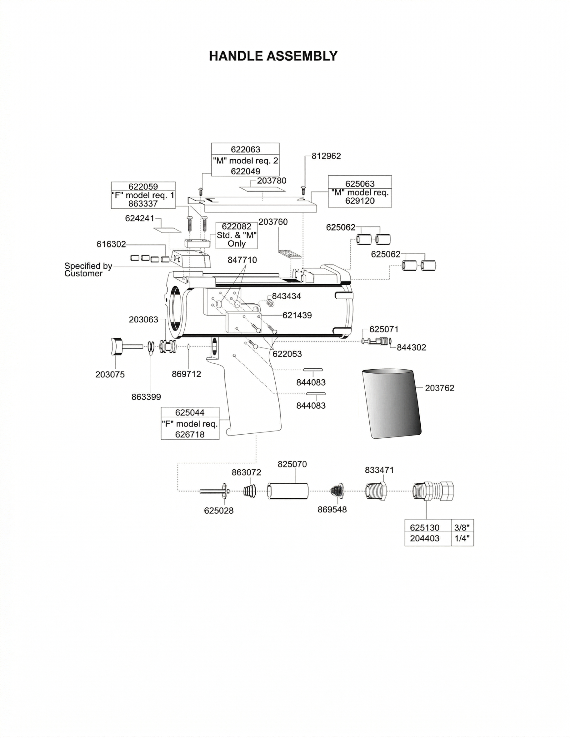
| Model No. | Name of Part | Qty. |
|---|---|---|
| 203075 | Trigger | 1 |
| 203083 | Trigger Casing | 1 |
| 203762 | Grip Sleeve | 1 |
| 203780 | Warning Label | 1 |
| 204403 | Swivel Fitting 1/4″ | 1 |
| 616302 | Support Block Bushing | 4 |
| 621439 | Cover Assembly | 1 |
| 622053 | Cover Assembly Screw | 3 |
| 622059 | Support Wedge Screw | 2 |
| 622063 | Spindle Cover Screw (Small) | 1 |
| 622082 | Support Wedge | 1 |
| 624241 | Warning Label | 1 |
| 625028 | Throttle Valve | 1 |
| 625044 | Handle | 1 |
| 625052 | Muffler Pad | 1 |
| 625062 | Spindle Needle Bearing (included in 625044) | 4 |
| 625063 | Spindle Cover | 1 |
| 625070 | Inlet Spacer | 1 |
| 625071 | Metering Valve | 1 |
| 625130 | Swivel Fitting 3/8″ | 1 |
| 625716 | “L” Model Handle | 1 |
| 629120 | “M” Model Spindle Cover | 1 |
| 812962 | Spindle Cover Screw (Large) | 1 |
| 833471 | Inlet Bushing | 1 |
| 843434 | Handle Pipe Plug | 1 |
| 844083 | Dowel Pin | 2 |
| 844302 | “O”-Ring 3/16″ x 5/16″ | 1 |
| 847710 | “O”-Ring 1/2″ x 5/8″ | 2 |
| 863072 | Throttle Valve Spring | 2 |
| 863337 | Support Wedge Screw (“L” model req. only 1) | 2 |
| 863399 | “O”-Ring 7/16″ x 9/16″ | 2 |
| 869548 | Inlet Screen | 1 |
| 869712 | “O”-Ring 1/16″ x 3/16″ | 1 |
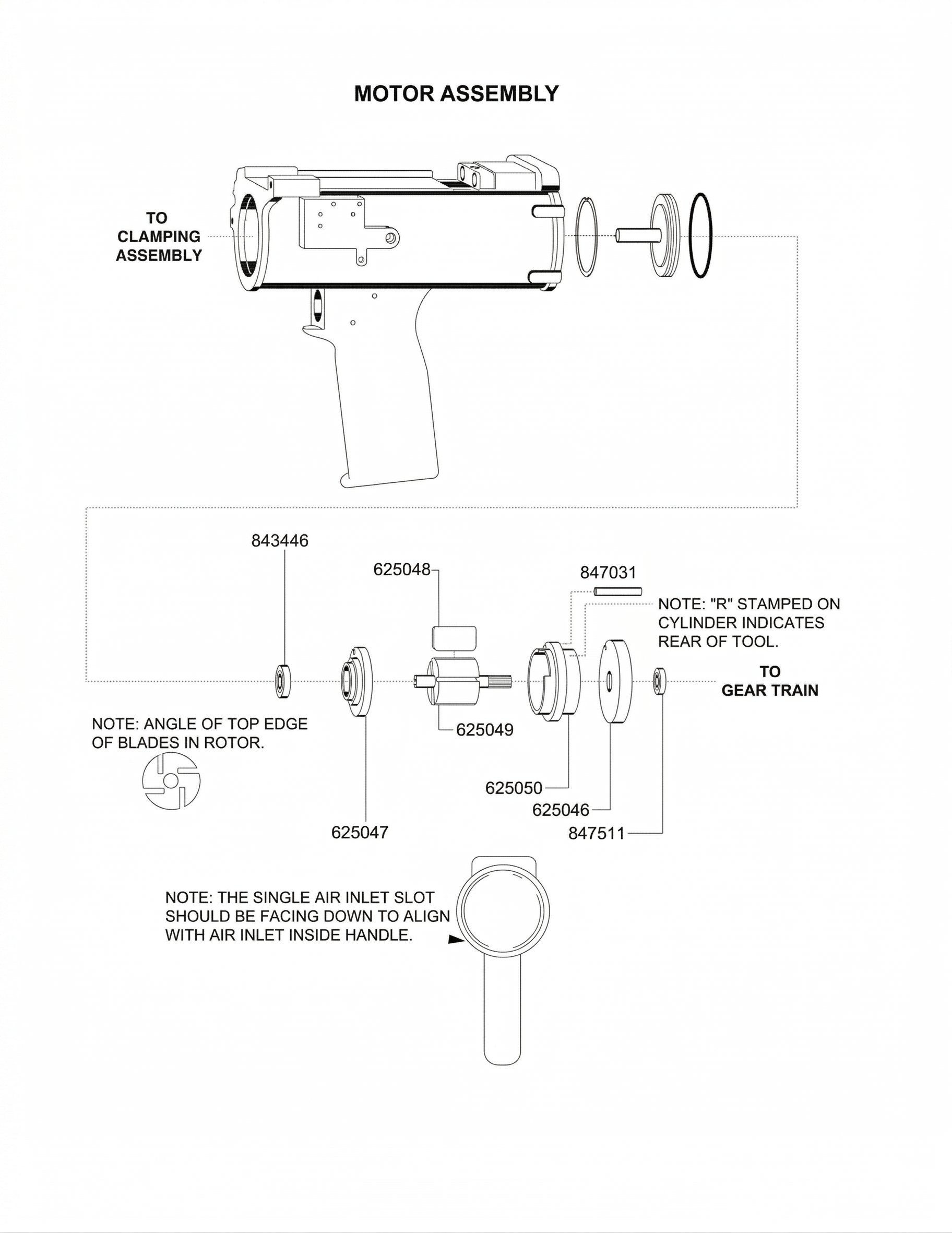
| Model No. | Name of Part | Qty. |
|---|---|---|
| 625046 | Front Bearing Plate | 1 |
| 625047 | Rear Bearing Plate | 1 |
| 625048 | Rotor Blade | 4 |
| 625049 | Rotor | 1 |
| 625050 | Cylinder (incl. 847031) | 1 |
| 843446 | Rear Rotor Ball Bearing | 1 |
| 847031 | Cylinder Pin | 1 |
| 847511 | Front Rotor Ball Bearing | 1 |
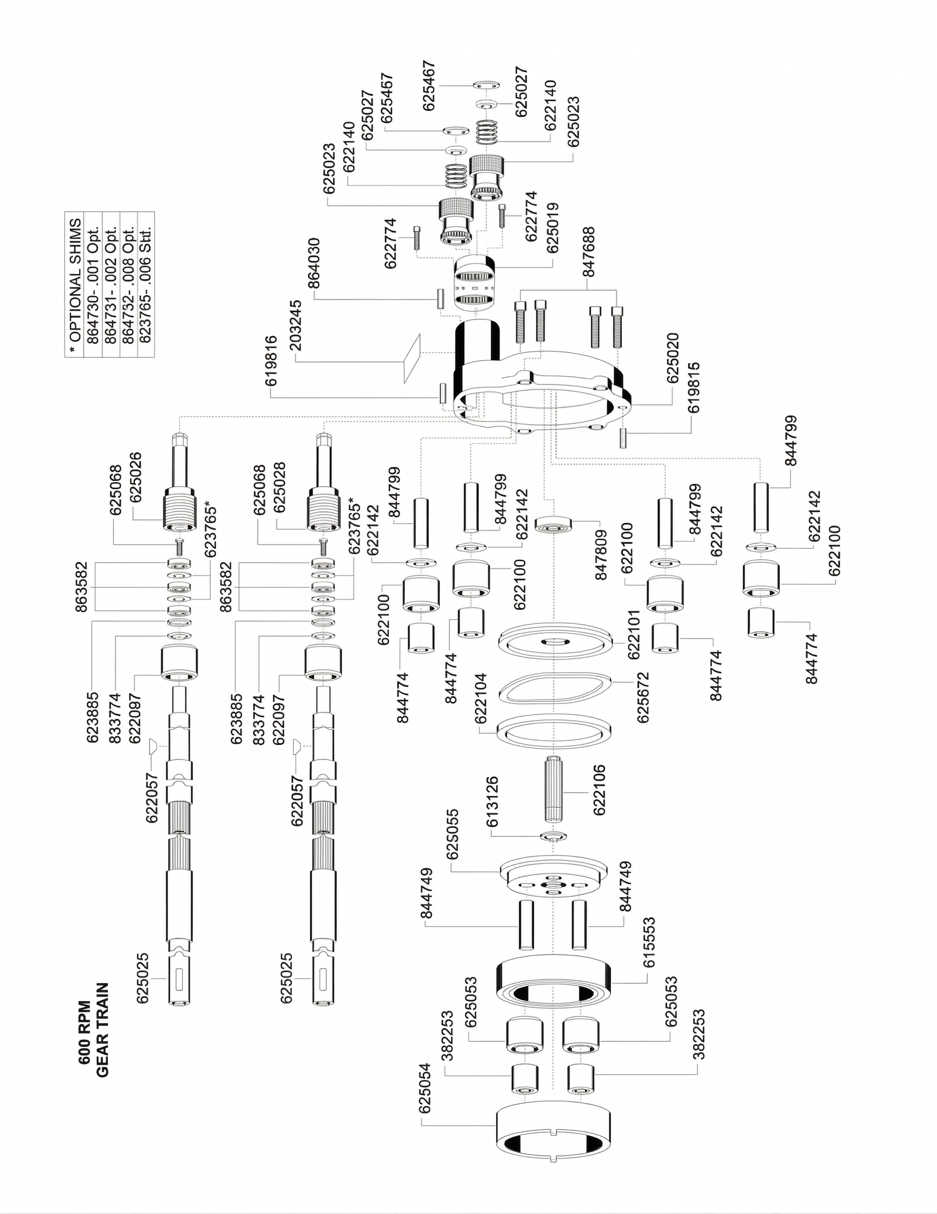
| Model No. | Name of Part | Qty. |
|---|---|---|
| 203245 | Caution Label (included in 625020) | 1 |
| 382253 | Planet Wheel Bearing | 2 |
| 613126 | Gear Pinion Spur Retainer Ring | 1 |
| 615553 | Carrier Bearing | 1 |
| 619816 | Backhead Dowel Pin (included in 625020) | 2 |
| 622057 | Spindle Key | 2 |
| 622097 | Spindle Gear | 2 |
| 622100 | Idler Gear | 4 |
| 622101 | Gear Plate | 1 |
| 622104 | Planet Carrier Spacer | 1 |
| 622106 | Gear Pinion Spur | 1 |
| 622140 | Adjustment Knob Spring | 2 |
| 622142 | Idler Gear Spacer | 4 |
| 622774 | Hex Head Cap Screw | 2 |
| 623685 | Spindle Bearing Retainer Ring | 2 |
| 623765 | Spindle Bearing Spacer .006″ (Standard) | Var. |
| 625019 | Spindle Adjustment Plate | 1 |
| 625020 | Backhead (incl. 619816, 864030, 847609) | 1 |
| 625023 | Spindle Adjustment Knob | 2 |
| 625025 | Spindle | 2 |
| 625026 | Spindle Adjustment Screw | 2 |
| 625027 | Spindle Adjustment Nut | 2 |
| 625053 | Planet Wheel | 2 |
| 625054 | Internal Gear | 1 |
| 625055 | Planet Carrier | 1 |
| 625068 | Spindle Bearing Retainer Screw | 2 |
| 625467 | Spindle Adjustment Knob Retainer Ring | 2 |
| 625872 | Wavy Washer | 3 |
| 833774 | Spindle Gear Retainer Ring | 2 |
| 844749 | 1st Reduction Idler Gear Pin | 2 |
| 844774 | Idler Gear Bearing | 4 |
| 844799 | Idler Gear Pin (4 included in 625020) | 4 |
| 847609 | Backhead Bearing (included in 625020) | 1 |
| 847688 | Backhead Bolt | 4 |
| 863582 | Spindle Bearing | 6 |
| 864030 | Dowel Pin | 1 |
| 864730 | Spindle Bearing Spacer .001″ (Opt.) | Var. |
| 864731 | Spindle Bearing Spacer .002″ (Opt.) | Var. |
| 864732 | Spindle Bearing Spacer .005″ (Opt.) | Var. |
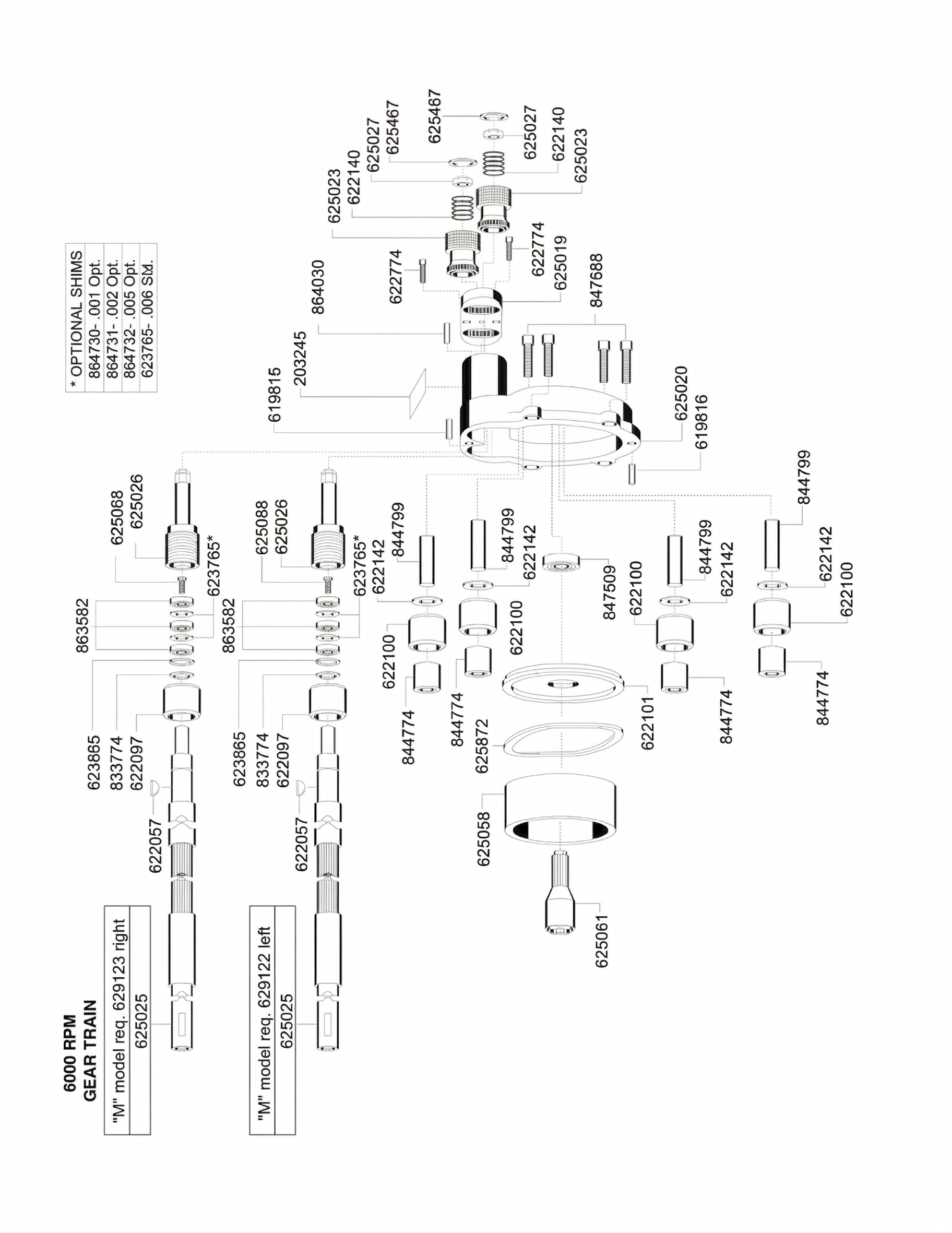
| Model No. | Name of Part | Qty. |
|---|---|---|
| 203245 | Caution Label (included in 625020) | 1 |
| 619816 | Backhead Dowel Pin (included in 625020) | 2 |
| 622057* | Spindle Key | 2 |
| 622097* | Spindle Gear | 2 |
| 622100 | Idler Gear | 4 |
| 622101 | Gear Plate | 1 |
| 622140 | Adjustment Knob Spring | 2 |
| 622142 | Idler Gear Spacer | 4 |
| 622774 | Hex Head Cap Screw | 2 |
| 623685* | Spindle Bearing Retainer Ring | 2 |
| 623765 | Spindle Bearing Spacer .006″ (Standard) | Var. |
| 625019 | Spindle Adjustment Plate | 1 |
| 625020 | Backhead (incl. 619816, 864030, 847609) | 1 |
| 625023 | Spindle Adjustment Knob | 2 |
| 625025 | Spindle | 2 |
| 625026* | Spindle Adjustment Screw | 2 |
| 625027 | Spindle Adjustment Nut | 2 |
| 625058 | Gear Plate Spacer | 1 |
| 625061 | Pinion Gear | 1 |
| 625068* | Spindle Bearing Retainer Screw | 2 |
| 625467 | Spindle Adjustment Knob Retainer Ring | 2 |
| 625872 | Wavy Washer (“F” model requires only 1) | 3 |
| 629122* | Spindle Left (“M” model only) | 1 |
| 629123* | Spindle Right (“M” model only) | 1 |
| 833774* | Spindle Gear Retainer Ring | 2 |
| 844774 | Idler Gear Bearing | 4 |
| 844799 | Idler Gear Pin (4 included in 625020) | 4 |
| 847609 | Backhead Bearing (included in 625020) | 1 |
| 847688 | Backhead Bolt | 4 |
| 863582* | Spindle Bearing | 6 |
| 864030 | Dowel Pin | 1 |
| 864730 | Spindle Bearing Spacer .001″ (Opt.) | Var. |
| 864731* | Spindle Bearing Spacer .002″ (Opt.) | Var. |
| 864732 | Spindle Bearing Spacer .005″ (Opt.) | Var. |
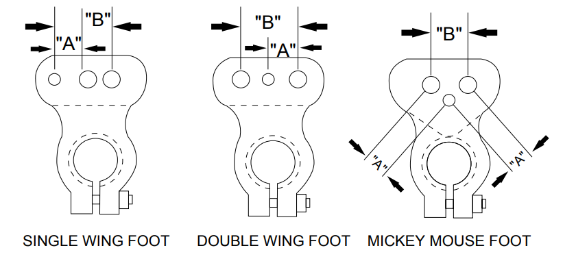
Nut plate dimension ranges:
| Single Wing | Double Wing | Mickey Mouse | ||
|---|---|---|---|---|
| A | Min. | .344″ | — | .212″ |
| Max. | .500″ | — | .538″ | |
| B | Min. | .312″ | .343″ | .300″ |
| Max. | 1.000″ | 1.125″* | 1.000″ |
* Note: For a spacing greater than 1.000″, fixed rivet hole spacing will be provided.
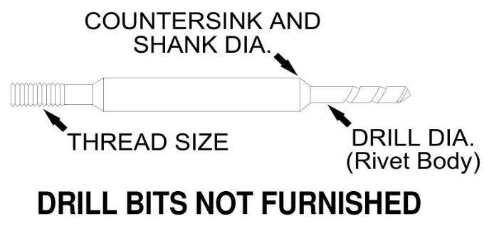
| Drill Series | Cutter Number | Shank & C-Sink Dia. | Drill Dia. | Thd. Size |
|---|---|---|---|---|
| 1 | QD51 | .1250″ | .067″ | #3-56 |
| 2 | QDS51 | .187″ | .067″ | #8-32 |
| 3 | QD40 | .187″ | .098″ | #8-32 |
| 4 | QDS40 | .250″ | .098″ | #8-32 |
| 5 | QD30 | .250″ | .1285″ | #8-32 |
Collet grip range (thickness of drilled material):
| Collet Length Code | Minimum | Maximum |
|---|---|---|
| 1 = -23 length | .02″ | .27″ |
| 2 = -40 length | .27″ | .52″ |
| 3 = -63 length | .52″ | .77″ |
| 4 = -90 length | .77″ | 1.02″ |
For replacement parts, service, or technical support, contact the nearest Quackenbush sales and service center:
Fort Worth, Texas
United States
Address 3133 S Grove St, Fort Worth, TX 76110 Phone 817.274.7418Ozoir-la-Ferrière
France
Address Zone Industrielle, 25 avenue Maurice Chevalier, 77330 Ozoir-la-Ferrière, France Phone +33.164.432.217Visit corvaer.com for additional product information and support.

Precision Tools. Trusted Performance.
corvaer.com
© 2026 Corvaer. All rights reserved. No part of this document may be reproduced without written permission.